
Workshop Manual


7A–66
AUTOMATIC TRANSMISSION (4L30–E)
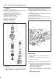
242RW004
47.Install two check balls (44).
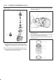
244RW002
48.Inspect main case electrical connector and seal,
replace if necessary.
B Install electrical 7 way connector/main case and
wiring harness.
49.Install two J–25025–B guide pins into main case.
B Install main case valve body complete assembly
(45) and manual valve link.
NOTE: Valve must be extended as the short end of
manual valve link is connected to the range selector lever.
Long end of link goes into valve.
B Install seven 13 mm screws.
Torque: 20 N•m (15 lb ft)
B Remove two guide pins.
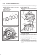
50.Install servo cover gasket, cover (46) and four 13 mm
screws.
Torque: 25 N•m (18 lb ft)
51.Connect wiring harness (47) to band control, shift
solenoids, and main case 7 way connector.
52.Install manual detent roller and spring assembly (48)
with clip.
B Install two 13 mm screws.
Torque: 20 N•m (15 lb ft)
53.Install oil filter (49), and three 13 mm screws.
Torque: 20 N•m (15 lb ft)
54.Install oil pan gasket, magnet, main oil pan (50), and
sixteen 10 mm screws.
Torque: 11 N•m (96 lb in)
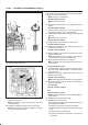
55.Inspect adapter case electrical connector and seal.
Replace if necessary.
B Install electrical 4 way connector and harness
assembly (52) in bottom of adapter case.
56.Install gasket, transfer plate, and gasket.
B Install adapter case valve body (51) and seven 13
mm screws.
Torque: 20 N•m (15 lb ft)
57.Connect wiring harness harness assembly (52) to
converter clutch PWM solenoid, force motor, and 4
way connector.
58.Install oil pan gasket, adapter case oil pan (53), and
twelve 10 mm screws.
Torque: 11 N•m (96 lb in)
B Rotate transmission, with bottom pan facing down.
59.Install mode switch (54), two 10 mm screws, selector
lever nut, and cover.
10 mm screw
Torque: 13 N•m (113 lb in)
Nut
Torque: 23 N•m (17 lb ft)
B Adjust using setting tool, refer to
Mode Switch in
this section.
60.Install O–ring (55) on turbine shaft.
61.Install torque converter (56).
The converter assembly must be replaced under any
of the following conditions:
a. Evidence of damage to the pump assembly.
b. Metal particles are found after flushing the cooler
lines.
c. External leaks in hub weld area.
d. Converter pilot broken, damaged, or poor fit into
crankshaft.