
Workshop Manual


7A–73
AUTOMATIC TRANSMISSION (4L30–E)
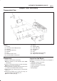
Adapter Case Valve Body
Disassembled View
243RY001
Legend
(1) Bracket
(2) Converter Clutch PWM Solenoid
(3) Retainer
(4) Force Motor Solenoid
(5) Retainer
(6) Plug
(7) 3/4 Accumulator Valve
(8) 3/4 Accumulator Control Valve
(9) Spring
(10) Retaining Ring
(11) Feed Limit Valve
(12) Plug Retainer
(13) O–Ring
(14) Plug
(15) Force Motor Screen Assembly
(16) Adapter Case Valve Body
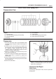
Disassembly
1.Remove 11mm bolt from valve body.
B Remove bracket (1) and converter clutch PWM
solenoid (2).
2.Remove 11mm bolt and retainer (3) from valve body.
B Remove force motor solenoid (4).
3.Remove retainer (5), plug (6), 3/4 accumulator valve
(7), and 3/4 accumulator control valve (8).
4.Remove spring (9), retaining ring (10), and feed limit
valve (11).
5.Remove plug retainer (12), O–ring (13), plug (14),
and force motor screen assembly (15).
B Use 5 mm bolt to pull plug.
Inspection And Repair
Inspect for the following, and replace any damaged or
worn parts:
1.Damage or wear to each valve.
2.Damage in oil passeges.
3.Cracks or damage to valve body.
4.Valve operations.
5.Spring fatigue.