
Workshop Manual


TRANSMISSION CONTROL SYSTEM (4L30–E)
7A1–45
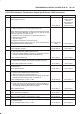
DTC P0722 Automatic Transmission Output Speed Sensor (OSS) Low Input
D07R200006
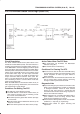
Circuit Description
Output speed information is provided to the PCM by the
OSS, which is a permanent magnet (PM) generator. The
PM generator produces a pulsing AC voltage. The AC
voltage level and number of pulses increases as the
speed of the vehicle increases. The PCM then converts
the pulsing voltage to output speed, which is used for
calculations. The vehicle speed can be displayed with a
scan tool.
This DTC detects a low output speed when there is a high
engine speed in a drive gear range. This is a type “B”
DTC.
Conditions For Setting The DTC
B No MAP DTCs P0107 or P0108, P0106, P1106,
P1107.
B No TPS DTCs P0122 or P0123.
B Not in Park or Neutral.
B TP angle is greater than 10%.
B Engine vacuum is between 0 and 70kPa.
B Engine speed is between 3000 and 7000 rpm.
B Transmission output speed is less than 0 rpm.
B All conditions met for 5 seconds.
Action Taken When The DTC Sets
B Fixed to 4th gear.
B Maximum line pressure.
B Inhibit TCC engagement.
B For lamp illuminate refer to
DTC type definition (type
B).
Conditions For Clearing The MIL/DTC
B The PCM will turn off the MIL and CHECK TRANS
Lamp after three consecutive ignition cycles without a
failure reported.
B The DTC can be cleared from the PCM history by
using a scan tool. The DTC will be cleared from
history when the vehicle has achieved 40 warmup
cycles without a failure reported.
B The PCM will cancel the DTC default actions when
the fault no longer exists and the ignition is cycled “off”
long enough to power down the PCM.
Diagnostic Aids
B An OSS DTC P0722 will set when no output speed is
at detected at start off.
B Inspect the wiring for poor electrical connection at the
PCM. Look for possible bent, backed out, deformed
or damaged terminals. Check for weak terminal
tension as well. Also check for a chafed wire that
could short to bare metal or other wiring. Inspect for a
broken wire inside the insulation.
B When diagnosing for a possible intermittent short or
open condition, move or massage the wiring harness
while observing test equipment for a change.
Test Description
The numbers below refer to the step numbers on the
diagnostic chart:
4. This test checks the OSS circuit.
5. This test checks the integrity of the OSS.
7. This test checks the 5–volt and ground circuit of the
PCM.