
Workshop Manual


TRANSMISSION CONTROL SYSTEM (4L30–E)
7A1–49
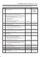
DTC P0723 Automatic Transmission Output Speed Sensor (OSS) Intermittent
Step Action Yes No
1 Were you sent here from the “Powertrain On–Board Diagnostic
(OBD) System Check”?
Go to
Step 2
Go to
OBD
System Check
Refer to
Driveability and
Emissions in
Engine section
2 1. Install the scan tool.
2. With the engine “off”, turn the ignition switch “on”.
NOTE: Before clearing DTC(s), use the scan tool to record “Freeze
Frame” and “Failure Records” for reference, as data will be lost
when the “Clear Info” function is used.
3. Record the DTC “Freeze Frame” and “Failure Records”.
4. Raise the drive wheels.
5. Start the engine.
6. Place the transmission in any drive range.
With the drive wheels rotating, does the “Trans Output Speed”
increase with the drive wheel speed?
Go to
Diagnostic
Aids
Go to
Step 3
3 Check for the most current and/or incorrect calibration.
Is the calibration current?
Go to
Step 16
Go to
Step 4
4 1. Turn the ignition “off”.
2. Disconnect the E35 (RED) PCM connector.
3. Using the J39200 DVOM, measure the resistance between
harness connector terminals E35–22 and E35–55.
Is the reading 3,000 ohms?
Go to
Step 5
Go to
Step 6
5 1. Select AC volts.
2. Rotate the rear wheels, ensuring the driveshaft is turning.
Is the voltage greater than 0.5 volts?
Go to
Step 7
Go to
Step 8
6 Inspect circuits BLU/YEL and BLU/GRN for a poor connection or
an open circuit.
Was a problem found?
Go to
Step 17
Go to
Step 8
7 1. Reconnect the E35 (RED) PCM connector.
2. Disconnect the OSS harness from the OSS.
3. With the engine “off”, turn the ignition “on”.
4. Using the J 39200 DVOM, measure the voltage at the OSS
harness connector terminals E44–1 and E44–2.
Is the reading between 4.0 to 5.1 volts? Go to
Step 16
Go to
Step 10
8 1. Remove the OSS.
2. Check the output shaft speed sensor rotor for damage or
misalignment. Refer to
Speed Sensor (Extension Assembly)
in Automatic Transmission (4L30–E) section.
Was a problem found?
Go to
Step 17
Go to
Step 9
9 Replace the OSS.
Is the replacement complete?
Go to
Step 17
—
10 Was the reading in step 7 less than 4.0 volts? Go to
Step 12
Go to
Step 11
11 Was the reading in Step 7 greater than 5.1 volts? Go to
Step 15
—
12 Using the J 39200 DVOM to chassis ground, measure the voltage
on circuit BLU/YEL.
Is the reading between 4.0 to 5.1 volts?
Go to
Step 13
Go to
Step 14