
Workshop Manual


2A–40
POWER–ASSISTED STEERING SYSTEM
Lock Cylinder
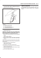
Lock Cylinder and Associated Parts
431RX005
Legend
(1) Inflator Module
(2) Steering Wheel
(3) Steering Column Cover
(4) Combination Switch and SRS Coil Assembly
(5) Snap Ring
(6) Cushion Rubber
(7) Lock Cylinder Assembly
(8) Instrument Panel Lower Cover
(9) Driver Knee Bolster (reinforcement)
(10) Shift Lock Cable (for A/T)
Removal
1.Turn the steering wheel so that the vehicle’s wheels
are pointing straight ahead.
2.Turn the ignition switch to “LOCK”.
3.Disconnect the battery ground cable, and wait at least
5 minutes.
4.Disconnect the yellow 2-way SRS connector located
under the steering column.
CAUTION: The wheels of the vehicle must be
straight ahead and the steering column in the
”LOCK” position before disconnecting the steering
wheel. Failure to do so will cause the coil assembly
to become uncentered which will cause damage to
the coil assembly.
5.Remove the engine hood opening lever and steering
lower cover.
6.Remove driver knee bolster (reinforcement).