
Workshop Manual


2A–46
POWER–ASSISTED STEERING SYSTEM
13.Remove the combination switch assembly with SRS
coil.
825RW288
14.Remove snap ring.
15.Remove cushion rubber.
16.Remove shift lock cable (For A/T).
17.Disconnect the starter switch harness connector
located under the steering column, then remove lock
cylinder assembly.
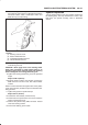
18.Apply a setting mark across the second steering shaft
and transfer gear assembly to reassemble the parts
in their original position, then remove the steering
column assembly and second steering shaft.
NOTE: A setting mark can be easily made if the shaft is
withdrawn a little by loosening the steering shaft universal
joint.
431RW009
Inspection
If the abnormal conditions are found through inspection,
replace the steering column assembly.
Column Capsule
Check capsules on steering column bracket assembly; all
must be securely seated in bracket slots and checked for
any loose conditions when pushed or pulled by hand.
431RW030
Check clearance between capsule and bracket. If must
be within 1mm (0.039 in).
431RW031