
Workshop Manual


SUPPLEMENTAL RESTRAINT SYSTEM
9J–8
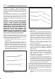
tool reads serial data from the SDM “Serial Data” line
terminal “24” to the data link connector terminal “9”.
Use of Special Tools
WARNING: TO AVOID DEPLOYMENT WHEN
TROUBLESHOOTING THE SRS, DO NOT USE
ELECTRICAL TEST EQUIPMENT SUCH AS A
BATTERY–POWERED OR AC–POWERED
VOLTMETER, OHMMETER, ETC, OR ANY TYPE OF
ELECTRICAL EQUIPMENT OTHER THAN THAT
SPECIFIED IN THIS MANUAL. DO NOT USE A NON
POWERED PROVE–TYPE TESTER. INSTRUCTIONS
IN THIS MANUAL MUST BE FOLLOWED
CAREFULLY, OTHERWISE PERSONAL INJURY MAY
RESULT. YOU SHOULD BE FAMILIAR WITH THE
TOOLS LISTED IN THIS SECTION UNDER THE
HANDLING SRS SPECIAL TOOLS.
You should be able to measure voltage and resistance.
You should be familiar with proper use of a scan tool such
as the Tech 2 Diagnostic Computer, SRS
Driver/Passenger Load Tool J–41433, Connector Test
Adapter Kit J–35616–A, and the DVM (Digital Multimeter)
J–39200.
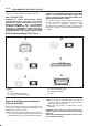
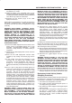
SRS Connector Body Face Views
D09RW003
Legend
(1) SDM
(2) Driver Air Bag Assembly
(3) Passenger Air Bag Assembly
(4) “Air Bag” Warning Lamp
(5) SRS Coil Assembly
(6) DLC
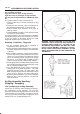
Repairs and Inspections Required
After an Accident
NOTE: If any SRS components are damaged, they must
be replaced. If SRS component mounting points are
damaged, they must be replaced.
B Never use SRS parts from another vehicle. This does
not include remanufactured parts purchased from an
authorized dealer; they may be used for SRS repairs.
B Do not attempt to service the SDM, the SRS coil
assembly, or the air bag assembly. Service of these
items is by replacement only.
B Verify the part number of replacement air bag
assembly.
CAUTION: Never use the air bag assembly from
another vehicle and difference model year air bag
assembly.
The air bag assembly has identification colors on the
bar code label as follows.