
Workshop Manual


REAR SUSPENSION
3D–1
AXIOM (Vehicles Produced Before July/31/2001)
SUSPENSION
REAR SUSPENSION
CONTENTS
Service Precaution 3D–1. . . . . . . . . . . . . . . . . . . . . .
General Description 3D–1. . . . . . . . . . . . . . . . . . . . .
Diagnosis 3D–2. . . . . . . . . . . . . . . . . . . . . . . . . . . . . .
Coil Spring 3D–5. . . . . . . . . . . . . . . . . . . . . . . . . . . . .
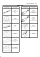
Coil Spring and Associated Parts 3D–5. . . . . . . .
Removal 3D–5. . . . . . . . . . . . . . . . . . . . . . . . . . . . .
Inspection and Repair 3D–6. . . . . . . . . . . . . . . . . .
Installation 3D–6. . . . . . . . . . . . . . . . . . . . . . . . . . . .
Shock Absorber 3D–7. . . . . . . . . . . . . . . . . . . . . . . . .
Shock Absorber and Associated Parts 3D–7. . . .
Removal 3D–7. . . . . . . . . . . . . . . . . . . . . . . . . . . . .
Inspection and Repair 3D–7. . . . . . . . . . . . . . . . . .
Installation 3D–7. . . . . . . . . . . . . . . . . . . . . . . . . . . .
Trailing Link 3D–8. . . . . . . . . . . . . . . . . . . . . . . . . . . .
Trailing Link and Associated Parts 3D–8. . . . . . .
Removal 3D–8. . . . . . . . . . . . . . . . . . . . . . . . . . . . .
Inspection and Repair 3D–8. . . . . . . . . . . . . . . . . .
Installation 3D–9. . . . . . . . . . . . . . . . . . . . . . . . . . . .
Upper Link 3D–10. . . . . . . . . . . . . . . . . . . . . . . . . . . . .
Upper Link and Associated Parts 3D–10. . . . . . . .
Removal 3D–10. . . . . . . . . . . . . . . . . . . . . . . . . . . . .
Inspection and Repair 3D–10. . . . . . . . . . . . . . . . . .
Installation 3D–11. . . . . . . . . . . . . . . . . . . . . . . . . . . .
Lateral Rod 3D–12. . . . . . . . . . . . . . . . . . . . . . . . . . . . .
Lateral Rod and Associated Parts 3D–12. . . . . . .
Removal 3D–12. . . . . . . . . . . . . . . . . . . . . . . . . . . . .
Inspection and Repair 3D–12. . . . . . . . . . . . . . . . . .
Installation 3D–13. . . . . . . . . . . . . . . . . . . . . . . . . . . .
Stabilizer Bar 3D–14. . . . . . . . . . . . . . . . . . . . . . . . . . .
Stabilizer Bar and Associated Parts 3D–14. . . . . .
Removal 3D–14. . . . . . . . . . . . . . . . . . . . . . . . . . . . .
Inspection and Repair 3D–14. . . . . . . . . . . . . . . . . .
Installation 3D–15. . . . . . . . . . . . . . . . . . . . . . . . . . . .
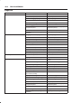
Main Data and Specifications 3D–16. . . . . . . . . . . . .
Special Tools 3D–18. . . . . . . . . . . . . . . . . . . . . . . . . . .
Service Precaution
WARNING: THIS VEHICLE HAS A SUPPLEMENTAL
RESTRAINT SYSTEM (SRS). REFER TO THE SRS
COMPONENT AND WIRING LOCATION VIEW IN
ORDER TO DETERMINE WHETHER YOU ARE
PERFORMING SERVICE ON OR NEAR THE SRS
COMPONENTS OR THE SRS WIRING. WHEN YOU
ARE PERFORMING SERVICE ON OR NEAR THE SRS
COMPONENTS OR THE SRS WIRING, REFER TO
THE SRS SERVICE INFORMATION. FAILURE TO
FOLLOW WARNINGS COULD RESULT IN POSSIBLE
AIR BAG DEPLOYMENT, PERSONAL INJURY, OR
OTHERWISE UNNEEDED SRS SYSTEM REPAIRS.
CAUTION: Always use the correct fastener in the
proper location. When you replace a fastener, use
ONLY the exact part number for that application.
ISUZU will call out those fasteners that require a
replacement after removal. ISUZU will also call out
the fasteners that require thread lockers or thread
sealant. UNLESS OTHERWISE SPECIFIED, do not
use supplemental coatings (Paints, greases, or other
corrosion inhibitors) on threaded fasteners or
fastener joint interfaces. Generally, such coatings
adversely affect the fastener torque and the joint
clamping force, and may damage the fastener. When
you install fasteners, use the correct tightening
sequence and specifications. Following these
instructions can help you avoid damage to parts and
systems.
General Description
The rear suspension is a 5-link, coil spring type
suspension with a stabilizer bar, consisting of two trailing
links, two upper links, lateral rod, shock absorber, and
stabilizer. In this suspension, the links are specially
arranged to enable the rear axle to move freely, thereby
expanding suspension stroke, reducing friction, and
improving lateral rigidity and roll control. All these result in
improved stability, riding comfort, and rough road
maneuverability.
Each link connects the axle housing with the frame
through a runner bushing. The axle housing is supported
by the trailing links and upper links longitudinally and by
the lateral rod latitudinally.
SECTION