
Workshop Manual


INTELLIGENT SUSPENSION
3F–29
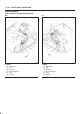
DTC9–2 Control Unit Blown Fuse for FL Actuator
Step Action Value(s) Yes No
1 1. Turn off the starter switch.
2. Disconnect the actuator connector C–31.
3. Measure the resistance between the actuator side
connector C–31 terminals 1 and 2.
Is the resistance within the specified value?
6.4– 7.2W Go to
Step 2
Go to
Step 3
2 1. Measure the resistance between the actuator side
connector C–31 terminals 3 and 4.
Is the resistance within the specified value?
6.4– 7.2W Go to
Step 4
Go to
Step 3
3 Replace the actuator FL.
— Go to
Step 7
—
4 1. If all steps are correct, check the continuity between
the control unit connector C–46 terminal 1 and
connector-terminal C46–6, C46–19, C46–7,
C46–20.
Is there continuity?
—
Begin diagnosis
again
Go to
Step 5
Go to
Step 6
5 Repair the circuit.
— Go to
Step 7
—
6 Replace the control unit.
— Go to
Step 7
—
7 1. Reconnect all components, ensure all components
are properly mounted.
2. Clear the DTC.
Was this step finished?
—
Go to
“Basic
Diagnosis
FLow”.
Go to
Step 7