
Workshop Manual


4B2–51
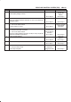
DRIVE LINE CONTROL SYSTEM (TOD)
Step Action Yes No
1 Is the TOD control unit the regular part? (Verity the part number.)
Go to
Step 2
Replace with the
regular part.
Go to
Step 2
2 1. Turn on the starter switch.
Does the voltage between the terminal 28 and 47 accord with the
table 1 corresponding to the AT selector positions?
Go to
Step 3
Go to
Step 5
3 Does the voltage between the terminal 41 and 47 accord with the
table 1 corresponding to the AT selector positions?
Go to
Step 4
Go to
Step 6
4 Does the voltage between the terminal 27 and 47 accord with the
table 1 corresponding to the AT selector positions?
Refer to
“Trouble
intermittently
observed”.
Go to
Step 7
5 1. Disconnect the AT mode connector (E–41).
Does the continuity between the inhibitor switch terminal 5 (D)
and 8 (A) accord with the table 2 corresponding to the AT selector
positions?
Repair the circuit
between the
connector
terminal (C–37) 6
and (E–41) 8.
Go to
step 8
Replace the
inhibitor switch.
Go to
Step 8
6 1. Disconnect the AT mode connector (E–41).
Does the continuity between the inhibitor switch terminal 5 (D)
and 7 (B) accord with the table 2 corresponding to the AT selector
positions?
Repair the circuit
between the
connector
terminal (C–37)
19 and (E–41) 7.
Go to
Step 8
Replace the
inhibitor switch.
Go to
Step 8
7 1. Disconnect the AT mode connector (E–41).
Does the continuity between the inhibitor switch terminal 5 (D)
and 6 (C) accord with the table 2 corresponding to the AT selector
positions?
Repair the circuit
between the
connector
terminal (C–37) 5
and (E–41) 6.
Go to
Step 8
Replace the
inhibitor switch.
Go to
Step 8
8 1. Check that all the parts are mounted.
2. Clear the trouble code.
Is this step complete?
Verify the repair. Go to
Step 8