
Workshop Manual


DRIVE LINE CONTROL SYSTEM (TOD)
4B2–54
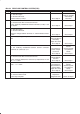
Step Action Yes No
1 1. Clear the trouble code.
2. Start the engine
3. Set the TOD mode.
Is there DTC31 (P1721)?
Go to
Step 2
Refer to
“Trouble
intermittently
observed”.
2 1. Turn off the starter switch.
2. Disconnect the ECU connector from ECU.
Is the continuity established between terminals (C–38)11 and
(C–38)22?
Go to
Step 3
Go to
Step 5
3 1. Connect the ECU connector.
2. Start the engine.
3. Set the TOD mode.
Does the voltage between terminals 11 and 22 indicate at least
0.4V?
Go to
Step 4
Go to
Step 6
4 Is the battery voltage always observed between terminals 11 and
22?
The harness is
short–circuited on
the battery.
Repair the circuit.
Go to
Step 8
Go to
Step 6
5 1. Disconnect the A–1 connector.
Is the continuity established between transfer connector
terminals (A–1)8 and (A–1)7?
The harness is
broken. Repair
the circuit.
Go to
Step 8
Replace the
transfer
electromagnetic
coil (solenoid
clutch).
Go to
Step 8
6 1. Turn off the starter switch.
2. Disconnect the ECU connector from ECU.
Is the resistance between the connector (C–38) terminal 11 and
22 1.0 ∼ 5.0W?
The ECU has
failed. Replace
the ECU
Go to
Step 8
Go to
Step 7
7 Is the resistance between the transfer connector (A–1) terminal 8
and 7 1.0 ∼ 5.0W?
The harness is
disconnection or
short to GND.
Repair the circuit.
Go to
Step 8
Replace the
transfer
electromagnetic
coil (solenoid
clutch).
Go to
Step 8
8 1. Check that all the parts are mounted.
2. Clear the trouble code.
Is this step complete?
Repeat the
“Diagnosis Flow”.
Return to Step 8