
Workshop Manual


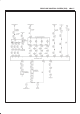


DRIVE LINE CONTROL SYSTEM (TOD)
4B2–78
Step Action Yes No
1 1. Turn on the starter switch.
When the TOD switch is selected to the TOD position, is 0V
observed between terminals 30 and 47, and 43 and 47? Does the
voltage between the terminals 7 and 47, 19 and 47, and 8 and 47
comply with the TOD mode in the following table?
Go to
Step 2
Repair the TOD
switch circuit.
Go to
Step 4
2 When the TOD switch is selected to the 2H position, is 12V
observed between terminals 30 and 47, and 0V observed
between terminals 43 and 47? Does the voltage between the
terminals 7 and 47, 19 and 47, and 8 and 47 comply with the 2H
mode in the following table?
Go to
Step 3
Repair the TOD
switch circuit.
Go to
Step 4
3 When the TOD switch is selected to the 4L position, is 0V
observed between the terminal 30 and 47 and 12V observed
between the terminal 43 and 47? Does the voltage between the
terminals 7 and 47, 19 and 47, and 8 and 47 comply with the 4L
mode in the following table?
The phenomenon
is not
reproduced.
Refer to
“Trouble
intermittentry
observed”.
Repair the TOD
switch circuit.
Go to
Step 4
4 1. Check that all the parts are mounted.
Is this step complete?
Verify repair. Go to
Step 4
Table: Indicator terminal voltage
Unit: V
TOD
switch
Terminals measured
sw
it
c
h
mode
Front 7
and 47
AUTO 19
and 47
Rear 8 and
47
2H 8.0 ∼ 14.5 8.0 ∼ 14.5 0
TOD 0 0 0
4L 0 8.0 ∼ 14.5 0