
Workshop Manual


4B2–95
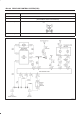
DRIVE LINE CONTROL SYSTEM (TOD)
Step Action Yes No
1 Start the engine.
When the TOD switch is selected to the TOD position, is 0V
observed between terminals 42 and 47?
Go to
Step 2
Go to
Step 4
2 1. The car stops, the AT selector is N position, and the brake is
applied.
2. Select the TOD switch to the 4L position.
Is 0V observed between terminals 42 and 47?
Go to
Step 3
Go to
Step 4
3 1. The car stops, the AT selector is N position, and the brake is
applied.
When the TOD switch is selected to the 4L position, is 12V
observed between the terminal 19 and 47?
The phenomenon
is not
reproduced.
Refer to
“Troubles
intermittently
observed”.
The ECU has
failed.Replace
the ECU.
Go to
Step 8
4 1. The car stops, the AT selector is N position, and the brake is
applied.
When the TOD switch is selected to the 2H position, is the battery
voltage observed between the terminal 23 and 47.
Go to
Step 5
Go to
Step 7
5 When the TOD switch is selected to the TOD position (TOD
mode), is 0 ∼ 1V observed between terminals 23 and 47?
Go to
Step 6
Go to
Step 7
6 1. The car stops, the AT selector is N position, and the brake is
applied.
When the TOD switch is selected to the 4L position, is 0V
observed between terminals 23 and 47?
Repair the circuit
or check the
“Front Axle
Disconnect”.
(Refer to
section
4B
)
Go to
Step 8
Go to
Step 7
7 Is any of the trouble codes 28 (P1760), 32 (P1761) and 33
(P1762) recorded?
Examine the
trouble based on
“Diagnosis from
Trouble Codes”.
The ECU has
failed. Replace
the ECU.
Go to
Step 8
8 Check that all the parts are mounted.
Is this step complete?
Verify the repair. Go to
Step 8