
Workshop Manual


4B2–113
DRIVE LINE CONTROL SYSTEM (TOD)
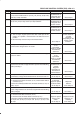
Step Action Yes No
1 1. Turn on the starter switch.
Is any of the trouble codes 41 (P1741), 42 (P1773), 43 (P1743)
and 55 (P1755) recorded?
Examine the
trouble based on
“Diagnosis from
Trouble Codes”.
Go to
Step 2
2 Is any of the trouble codes 13 (P1735), 14 (P1731), 15 (P1736),
16 (P1737), 24 (P1733), and 27 (P1738) recorded?
Examine the
trouble based on
“Diagnosis from
Trouble Codes”.
Go to
Step 3
3 Is the trouble code 17 (P1774) recorded? Examine the
trouble based on
“Diagnosis from
Trouble Codes”.
Go to
Step 4
4 1. Turn on the starter switch.
2. The car stops, engine speed is less than 1500 rpm, the AT
selector is N position, and select the TOD switch to the 4L
position.
Do the front lamp and rear lamp in the indicator blink?
Go to
Step 5
Examine the
trouble based on
“Trouble
Diagnosis
Depending on the
Status of TOD
Indicator”.
5 1. Step on the brake pedal.
Is the transfer changed to the 4L mode?
The phenomenon
is not
reproduced.
Refer to
“Trouble
intermittently
observed”.
Go to
Step 6
6 When the vehicle is moved forth and back, is the transfer changed
to the 4L mode?
The phenomenon
is not
reproduced.
Refer to
“Trouble
intermittently
observed”.
Go to
Step 7
7 Does the continuity corresponding to the encoder position
between the terminals comply with the 4L position in the following
table (continuity)?
Examine the
trouble based on
“Trouble
diagnosis
Depending on
The Status of
TOD Indicator”.
Go to
Step 8
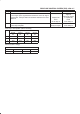
8 1. Step on the brake pedal.
Is the battery voltage observed between the terminal 37 and 47?
Go to
Step 10
Go to
Step 9
9 1. Turn off the starter switch.
2. Disconnect the ECU connector (C–37) and the brake switch
connector (I–31).
Is there the continuity between the connector terminal (C–37) 15
and (I–31) 4?
The brake switch
is abnormal.
Repair or replace
the brake switch.
Go to
Step 13
Repair the
harness.
Go to
Step 13
10 1. Select the AT selector to the N position.
Is the voltage between the terminals ranged within the following
table (voltage)?
Go to
Step 12
Go to
Step 11
11 1. Turn off the starter switch.
2. Disconnect the ECU connector (C–37).
3. Disconnect the AT mode switch connector (E–41).
Is there the continuity between the following connector terminals?
(C–37)6 and (E–41)8 (C–37)19 and (E–41)7 (C–37)5 and
(E–41)6
Repair or replace
the AT mode
switch.
Go to
Step 13
Repair the circuit
which has no
continuity.
Go to
Step 13