
Workshop Manual


4C–47
DRIVE SHAFT SYSTEM
If abnormal conditions are discovered during
inspection, go to Step 6. If there are no abnormal
conditions, reassemble the front disc rotor and
caliper.
NOTE: Hub, wheel bearing and spindle is integrated to
the hub unit bearing so it must not be disassembled. If it
has abnormal rattle or noise, replace the hub unit bearing.
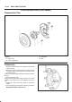
6.Remove the ABS sensor connector.
411R200004
Legend
(1) ABS Sensor Connector
(2) Bolt
7.Remove the 4 bolts fixing the hub unit bearing to the
knuckle.
Apply penetrating oil to the bearing and knuckle contact
surfaces if the surfaces are stuck together because of
rust.
8.Temporarily install long bolts to 2 of the fixing bolt
holes (the bolts must have the same diameter and
thread width).
9.Strike the long bolts with a hammer to loosen and
remove the hub unit bearing from the knuckle.
Take care not to drop the bearing.
10.If necessary, replace the wheel pin in the following
manner.
B Place hub on a suitable work surface and remove
wheel studs, as required, using a hammer.
411RS004
Inspection
Inspect the parts listed below for abrasion, breakage, and
other abnormal conditions.
Repair, or replace the parts as required.
B Disc
B Caliper
B Wheel pin
B Hub unit bearing