
Workshop Manual


HEATING, VENTILATION AND AIR CONDITIONING (HVAC)
1A–33
Leak Check
Inspection of refrigerant leak
Refrigerant leak may cause an adverse effect not only on
the performance and durability of each component of the
air–conditioner, but also on the global atmosphere.
Therefore, it is most important to repair refrigerant leak
when there is any leak found.
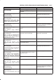
Inspection flow of refrigerant leak
Step Action Yes No
1 1. Evacuate the refrigerant system.
2. Charge the refrigerant.
Is there any refrigerant leak?
Repair refrigerant
system.
Go to
Step 2
2 1. Operate the compressor for more than 5 minutes to raise the
pressure on the high pressure side.
Is there any refrigerant leak at high pressure components?
Repair refrigerant
system.
Compressor
operation to be
confirmed.
Inspection Steps
Check the components of air–conditioner to see if there
occurs any refrigerant leak along the flow of refrigerant.
NOTE:
B To avoid refrigerant leak detection error, avoid
refrigerant vapor and cigarette smoke presence when
performing the inspection. Also, select a location that
is not susceptible to wind, in case refrigerant vapor is
found it will not be blown off.
B Inspection should be conducted chiefly on the pipe
connections and sections where a marked oil
contamination is found. When refrigerant is leaking,
oil inside is also leaking at the same time.
B It is possible to visually check the leak from inside the
cooling unit. Follow the method below when
performing the inspection. Remove the drain hose or
resistor of the cooling unit, and insert a leak detector
to see if there are signs of leakage.
High Pressure Side
1.Discharger section of compressor.
2.Inlet/outlet section of condenser.
3.Inlet/outlet section of receiver driver.
4.Inlet section of cooling unit.
Low Pressure Side
1.Outlet section of cooling unit.
2.Intake section of compressor.
Major Checking Points of Refrigerant Leak
Compressor
B Pipe connection
B Sealing section of shaft
B Mating section or cylinder
Condenser
B Pipe connection
B Welds of condenser body
Receiver driver
B Pipe connection
B Attaching section of pressure switch
B Section around the sight glass
Evaporator unit (cooling unit)
B Pipe connections
B Connections of expansion valve
B Brazed sections of evaporator
NOTE:
B The evaporator and expansion valve are contained in
the case. Remove the drain hose or the resistor of the
cooling unit and insert a leak detector when checking
for any leak.
Flexible hose
B Pipe connection
B Caulking section of the hose
B Hose (cracks, pinholes, flaws)
Pipe
B Pipe connection
B Pipe (cracks, flaws)
Charge valve
NOTE:
B The charge valve, which is used to connect the gauge
manifold, is normally provided with a resin cap. When
the valve inside gets deteriorated, refrigerant will leak
out.
Leak at Refrigerant Line Connections
1.Check the torque on the refrigerant line fitting and, if
too loose, tighten to the specified torque.
B Use two wrenches to prevent twisting and damage
to the line.
B Do not over tighten.
2.Perform a leak test on the refrigerant line fitting.