
Workshop Manual


5A–24
BRAKE CONTROL SYSTEM
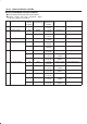
EHCU Connector Pin-out Checks
B Disconnect Electronic Hydraulic Control Module.
B Perform checks with high impedance digital
multimeter J-39200 or equivalent.
No. Circuit to be Tested Ignition
Switch
Position
Multimeter
Scale/Range
Measure
between Pin
Number
Nominal Value Note
1 Power supply OFF 20DCV 1 (C–5)
2 (C–5)
11.5V to 14.5V
2 Ignition enable
OFF 20DCV 1 (C–6)
7 (C–6)
0V to 0.1V
ON 20DCV 1 (C–6)
7 (C–6)
11.5V to 14.5V
3 Stoplamp switch OFF 20DCV 13 (C–6)
7 (C–6)
10.5V to 14.5V Press brake pedal
4 Ground connection
OFF 200W 7 (C–6)
Ground
Less than 2W
OFF 1W 2 (C–5)
Ground
Less than 0.2W
5 FL speed sensor
OFF 2kW 2 (C–6)
10 (C–6)
2.0kW to 2.8kW Internal Resistance
OFF 200kW 2 (C–6)
7 (C–6)
more than
100kW
Insulation Resistance
OFF 200mACV 2 (C–6)
10 (C–6)
more than
200mV
Turn wheel at 1RPS
6 FR speed sensor
OFF 2kW 3 (C–6)
11 (C–6)
2.0kW to 2.8kW Internal Resistance
OFF 200kW 3 (C–6)
7 (C–6)
more than
100kW
Insulation Resistance
OFF 200mACV 3 (C–6)
11 (C–6)
more than
200mV
Turn wheel at 1RPS
7 RR speed sensor
OFF 2kW 4 (C–6)
12 (C–6)
1.2kW to 2.0kW Internal Resistance
OFF 200kW 4 (C–6)
7 (C–6)
more than
100kW
Insulation Resistance
OFF 200mACV 4 (C–6)
12 (C–6)
more than
200mV
Turn wheel at 1RPS