
Workshop Manual


5A–41
BRAKE CONTROL SYSTEM
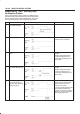
Chart B-6 G-Sensor Output Failure (DTC 21 (Flash out) / C0276 (Serial communications))
Step
Action
Yes No
1 1. Turn the key off.
2. Replace EHCU.
3. Reconnect all components, ensure all components are
properly mounted.
Was this step finished?
Repeat the “Basic
diagnostic flow
chart”
Go to
Step 1
Chart B-7 Brake Switch Failure (DTC 22 (Flash out) / C0281 (Serial communications))
Step
Action
Yes No
1 Is the stop light actuated when the brake pedal is depressed? Go to
Step 2
Go to
Step 4
2 1. Turn the key off.
2. Disconnected coil integrated module connector.
Is the check voltage between coil integrated module connector
(C-6) terminals 13 to 7 when brake pedal is depressed the battery
voltage?
Go to
Step 3
Harness between
brake SW and
coil integrated
module is faulty.
Go to
Step 6
3 Is the check that pins C-5 connector 2, and C-6 connector 7 have
good ground?
Check harness /
connector for
disconnection
Fault found:
Repair, and
perform system
self-check.
No fault found:
replace EHCU.
Go to
Step 6
Repair.
Go to
Step 6
4 Is stop light fuse normal?
Go to
Step 5
Replace.
Go to
Step 6
5 Is brake SW normal? Abnormal
harness in stop
light circuit.
Repair the
harness.
Go to
Step 6
Replace.
Go to
Step 6
6 1. Reconnect all components, ensure all components are
properly mounted.
2. Clear diagnostic trouble code.
Was this step finished?
Repeat the “Basic
diagnostic flow
chart”
Go to
Step 6