
Workshop Manual


5A–45
BRAKE CONTROL SYSTEM
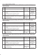
Chart B-16 Rear Dump Solenoid Coil Failure (DTC 46 (Flash out) / C0252, C0254 (Serial
communications))
Step
Action
Yes No
1 Was the “EHCU Connector Pin–out Checks” performed?
Go to
Step 2
Go to
“EHCU
Connector
Pin–out Checks.”
2 1. Turn the key switch to off.
2. Disconnect the 2–way EHCU connector (C–5) from the
EHCU.
3. Inspect the connector for damage or corrosion.
Is the connector free from damage or corrosion?
Go to
Step 3
Repair the
connector.
Repeat the “Basic
Diagnostic Flow
Chart.”
3 1. Replace the Coil Integrated Module.
2. Reconnect all components, ensure all components are
properly mounted.
Was this step finished?
Repeat the “Basic
diagnostic flow
chart”
Go to
Step 3
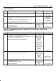
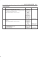
Chart B-17 FL Speed Sensor Open or Shorted (DTC 51 (Flash out) / C0225 (Serial
communications))
Step
Action
Yes No
1 1. Turn the key off.
2. Disconnect coil integrated module connector.
3. Measure the resistance between coil integrated module
connector (C-6) terminals 2 and 10.
Is the resistance between 2.0k and 2.8k ohms?
Check for faults
in harness
between speed
sensor and coil
integrated
module.
Fault found:
Repair, and
perform system
self-check.
No fault found:
Replace coil
integrated
module.
Go to
Step 3
Go to
Step 2
2 Measure the FL speed sensor resistance at the sensor connector.
Is the resistance between 2.0k and 2.8k ohms?
Repair harness
abnormality
between sensors
and coil
integrated
module.
Go to
Step 3
Replace sensor.
Go to
Step 3
3 1. Reconnect all components, ensure all components are
properly mounted.
2. Clear diagnostic trouble code.
Was this step finished?
Repeat the “Basic
diagnostic flow
chart”
Go to
Step 3