
Workshop Manual


5A–51
BRAKE CONTROL SYSTEM
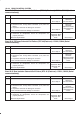
Chart B-23 Simultaneous Drop-out of Front Speed Sensor Signal (DTC 64 (Flash out) /
C0229 (Serial communications))
Step
Action
Yes No
1 1. Turn the key off.
2. Disconnect coil integrated module connector.
3. Measure the FL speed sensor resistance between coil
integrated module connector (C-6) terminals 2 and 10.
Is the resistance between 2.0k and 2.8k ohms?
Go to
Step 2
Go to
Step 3
2 Measure the FR speed sensor resistance between coil integrated
module connector (C-6) terminals 3 and 11.
Is the resistance between 2.0k and 2.8 k ohms?
Go to
Step 5
Go to
Step 4
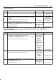
3 Measure the FL speed sensor resistance at the sensor connector.
Is the resistance between 2.0k and 2.8k ohms?
Repair harness
abnormality
between sensors
and coil
integrated
module.
Go to
Step 2
Replace sensor.
Go to
Step 2
4 Measure the FR speed sensor resistance at the sensor
connector.
Is the resistance between 2.0k and 2.8k ohms?
Repair harness
abnormality
between sensors
and coil
integrated
module.
Go to
Step 5
Replace sensor.
Go to
Step 5
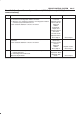
5 Damage and powered iron sticking to sensor/sensor ring? Repair.
Go to
Step 6
Go to
Step 6
6 Is there play sensor/sensor rotor? Repair.
Go to
Step 7
Go to
Step 7
7 Is sensor output normal? (Chart C-1-1&C-1-2 or TC-1) Check for faults
in harness
between speed
sensor and coil
integrated
module.
Fault found:
repair, and
perform system
self-check.
No fault found:
replace EHCU.
Go to
Step 8
Replace sensor.
Go to
Step 8
8 1. Reconnect all components, ensure all components are
properly mounted.
2. Clear diagnostic trouble code.
Was this step finished?
Repeat “Basic
diagnostic flow
chart”
Go to
Step 8
NOTE: Even after repairing the faulty part the warning
light (W/L) does not go out if the vehicle is at a stop. Turn
the ignition switch to the ON position and drive the vehicle
at 12 km/h (8 mph) or higher to make sure that the
warning light goes out.