
Workshop Manual


5A–52
BRAKE CONTROL SYSTEM
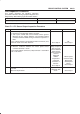
Chart B-24 Wheel Speed Input Abnormality (DTC 65 (Flash out) / C0238 (Serial
communications))
Step
Action
Yes No
1 Using TECH 2? Go to
Step 2
Go to
Step 3
2 1. Connect TECH 2.
2. Select Snap shot manual trigger.
3. With wheel speed data displayed, run the vehicle when speed
has arrived at 30 km/h (18 mph).
4. Check speed data on each wheel (refer to the criterion given
below). * 1
Is the abnormal sensor condition found?
Replace.
Go to
Step 8
Go to
Step 3
All the sensors
should follow the
following
flowchart (without
using TECH 2).
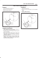
3 Is there play in sensor/sensor ring? Repair.
Go to
Step 8
Go to
Step 4
4 Is there powdered iron sticking to sensor/sensor ring? Repair.
Go to
Step 8
Go to
Step 5
5 Is there a broken tooth or indentation in sensor ring? Replace sensor
ring.
Go to
Step 8
Go to
Step 6
6 Is there play in wheel bearing? Adjust or repair.
Go to
Step 8
Go to
Step 7
7 Is the check wiring between sensor and coil integrated module
normal?
Replace EHCU.
Go to
Step 8
Repair, and
perform system
self-check.
Go to
Step 8
8 1. Reconnect all components, ensure all components are
properly mounted.
2. Clear diagnostic trouble code.
Was this step finished?
Repeat ‘Basic
diagnostic flow
chart”
Go to
Step 8
Sensor Signal Abnormality Criteria using TECH 2
1.While driving, the speed of one or two wheels is 25%
or more higher or lower than that of the other wheels.
2.The speed of one or two wheels is 10 km/h (6 mph) or
more higher or lower than that of the other wheels.
3. During steady driving, wheel speed changes abruptly.
*1 The vehicle must run on a level paved road.
NOTE: Even after repairing the faulty part the warning
light (W/L) does not go out if the vehicle is at a stop.
Turn the ignition switch to the ON position and drive the
vehicle at 12 km/h (8 mph) or higher to make sure that the
warning light goes out.
It is important to verify that the correct tires are installed
on vehicle.