
Workshop Manual


5A–53
BRAKE CONTROL SYSTEM
Unit Inspection Procedure
This section describes the following inspection
procedures referred to during
Symptom Diagnosis
and
Diagnosis By “ABS” Warning Light Illumination Pattern
without TECH 2 with TECH 2
Sensor Output Inspection Chart C-1-1 to C-1-3 Chart TC-1
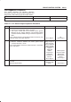
Chart C-1-1 FL Sensor Output Inspection Procedure
Step
Action
Yes No
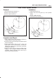
1 1. Turn the key off.
2. Disconnect coil integrated module connector.
3. Jack up the vehicle with all four wheels off the ground.
Measure the AC voltage between coil integrated module
connector terminals while turning FL wheel at a speed of 1
RPS:
Is the voltage between coil integrated module connector (C-6)
terminals 2 and 10 less than 200 mV?
Go to
Step 2
OK.
Go to
Step 3
2 1. Disconnect the wheel speed sensor.
2. Measure resistance between the wheel speed sensor
connector terminals 1 and 2.
Is the check between connector (C-28) terminals 1 and 2 within
2.0k - 2.8k ohms?
Connector is
faulty, or open or
short circuit of
harness between
wheel speed
sensor connector
and coil
integrated
module.
Inspect and
correct the
connector or
harness.
Go to
Step 3
Wheel speed
sensor is faulty.
Replace the
wheel speed
sensor.
Go to
Step 3
3 Reconnect all components, ensure all components are properly
mounted.
Was this step finished?
Repeat the “Basic
diagnostic flow
chart”
Go to
Step 3