
Workshop Manual


5C–55
POWER–ASSISTED BRAKE SYSTEM
NOTE: Do not over stretch the return spring.
305RS003
9.Remove upper (inner) return spring (9).
10. Remove hold-down spring and cup (3) and hold-down
pin (16).
11.Remove Trailing shoe assembly (7) with parking
brake lever (16).
12. Remove parking brake cable from parking brake lever
(11).
13.Remove retainer (14), wave washer (13), and parking
brake lever (11).
Brake Lining Inspection
Check the shoe assemblies for wear by removing brake
drum.
Replace the shoe assemblies, if lining thickness is less
than 1.0 mm (0.039 in).
The shoe assemblies have a wear indicator that makes a
noise when the linings wear to a degree where
replacement is required.
Minimum limit: 1.0 mm (0.039 in)
305RS001
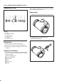
Installation
1.Apply grease lightly to back place A.
305RW002
Legend
(1) Place A (3 portions for each side)
2.Install parking brake lever (11), wave washer (13),
and retainer (14).
3.Install trailing shoe assembly (7) with parking brake
lever (16).
4.Install the parking brake cable to parking brake lever
(11).
5.Install hold-down pin (16) and hold-down spring and
cup (3).
6.Install upper (inner) return spring (9).
7.Install leading shoe assembly (8) with upper (inner)
return spring (9).
NOTE: Do not over stretch the return spring.
305RS003
8.Install adjuster assembly (12).
9.Install hold-down pin (15) and hold-down spring and
cups (4).