
Workshop Manual


6A–63
ENGINE MECHANICAL (6VE1 3.5L)
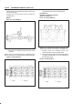
3. Measure the camshaft thrust clearance with a dial
indicator. Replace the camshaft and/or the
cylinder head if the camshaft thrust clearance
exceeds the specified limit.
Camshaft thrust Clearance
Standard : 0.03 mm–0.08 mm
(0.0012 in.–0.0031 in.)
Limit : 0.12 mm (0.0047 mm)
014RW035
Reassembly
1.Install camshaft drive gear assembly and tighten
three bolts to specified torque.
Torque: 10 N·m (89 lb in)
2.Install the spring ; camshaft gear(1) into the camshaft
assembly.
Ensure the clearance is between the right side of the
spring; camshaft gear (1) and the dowel pin (2).
014R100017
3.Align the dowel pin on the sub gear to the clearance of
the spring ; camshaft gear made in step 2 and install
the sub gear (3).
4.Install the wave washer (2). Use snap ring pliers to
install the snap ring (1).
014R100018
5.Tighten sub gear setting bolt.
a. Use J–42686 gear spring lever to pre-load the sub
gear. Turn the sub gear in a clockwise direction
until the M5 bolt hole aligns with the hole in the
camshaft driven gear.
b. Install the M5 bolt and tighten to a suitable torque to
prevent the sub gear from moving.
014RW041
6.Align the timing mark on the retainer and dowel pin of
the camshaft drive gear.
7.Install camshaft assembly and camshaft brackets,
tighten twenty bolts on one side bank to the specified
torque.