
Workshop Manual


6A–68
ENGINE MECHANICAL (6VE1 3.5L)
7.Remove oil gallery (7).
8.Remove piston and connecting rod assembly (8).
Refer to “Piston, Piston Ring and Connecting Rod” in
this manual.
9.Remove flywheel (9).
10.Remove rear oil seal retainer (10).
11.Remove main bearing cap (11).
12.Remove crankshaft (12).
Inspection and Repair for Bearings
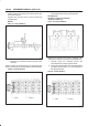
1.Inspect Crankshaft
Set the dial indicator as shown in the illustration and
measure the crankshaft thrust clearance. If the thrust
clearance exceeds the specified limit, replace the
thrust bearings as a set.
Thrust Clearance
Standard : 0.06 mm–0.24 mm
(0.0024 in–0.0094 in)
Limit : 0.30 mm (0.0118 in)
015RS003
Main Bearing Clearance
1.Remove the bearing caps and measure the oil
clearance.
2.Remove the main bearing cap fixing bolts in the
sequence shown in the illustration.
Arrange the removed main bearing caps in the
cylinder number order.
Remove the main bearings.
015RS004
3.Remove the crankshaft.
Remove the main bearings.
4.Clean the upper and lower bearings as well as the
crankshaft main journal.
5.Check the bearings for damage or excessive wear.
The bearings must be replaced as a set if damage or
excessive wear is discovered during inspection.
6.Set the upper bearings and the thrust washers to their
original positions.
Carefully install the crankshaft.
7.Set the lower bearings to the bearing cap original
position.
8.Apply plastigage to the crankshaft journal unit as
shown in the illustration.
NOTE: Do not set the plastigage on the oil hole.
015RS005