INDUSTRIAL DIESEL ENGINE AA-4BG1T, AA-6BG1 BB-4BG1T, BB-6BG1T MODELS WORKSHOP MANUAL ISUZU MOTORS LIMITED
TABLE OF CONTENTS SECTION ISUZU WORKSHOP MANUAL INDUSTRIAL DIESEL ENGINE AA-4BG1T, AA-6BG1 BB-4BG1T, BB-6BG1T MODELS NAME 1 GENERAL INFORMATION 2 MAINTENANCE 3 ENGINE ASSEMBLY I (DISASSEMBLY) 4 ENGINE ASSEMBLY II (INSPECTION & REPAIR) 5 ENGINE ASSEMBLY III (REASSEMBLY) 6 LUBRICATING SYSTEM 7 COOLING SYSTEM 8 FUEL SYSTEM 9 TURBOCHARGER FOREWORD This Workshop Manual is designed to help you perform necessary maintenance, service, and repair procedures on applicable Isuzu industrial engines
GENERAL INFORMATION 1–1 SECTION 1 GENERAL INFORMATION TABLE OF CONTENTS ITEM PAGE General repair instructions . . . . . . . . . . . . . . . . . . . . . . . . . . . . . . . . . . . . . . . . . . . . . . . . . . . . . . . . . . . . . . . . . . . . . . . . . . . . . . . 1– 2 Notes on the format of this manual. . . . . . . . . . . . . . . . . . . . . . . . . . . . . . . . . . . . . . . . . . . . . . . . . . . . . . . . . . . . . . . . . . . . . 1– 2 Main data and specifications . . . . . . . . . . . . . . .
1–2 GENERAL INFORMATION GENERAL REPAIR INSTRUCTIONS 1. Before performing any service operation with the engine mounted, disconnect the grounding cable from the battery. This will reduce the chance of cable damage and burning due to short circuiting. 2. Always use the proper tool or tools for the job at hand. Where specified, use the specially designed tool or tools. 3. Use genuine ISUZU parts referring ISUZU PARTS CATALOG for the engines surely. 4.
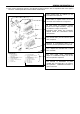
GENERAL INFORMATION 1–3 6. Each service operation section in this Workshop Manual begins with an exploded view of the applicable area. A brief explanation of the notation used follows. ENGINE ASSEMBLY ( 1 ) • Parts marked with an asterisk (*) are included in the repair kit. • Parts within a square frame are to be removed and installed as a single unit. • All parts within an irregularly shaped frame form a single assembly. They are considered a "major component".
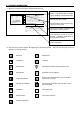
1–4 GENERAL INFORMATION 7. Below is a sample of the text of the Workshop Manual. • Valve Guide Installation 1. Lubricate the valve guide outer face with engine oil. This is the item shown in the illustration. It is marked with a triangle (▲) on the Major Components page. 2. Attach the installer to the valve guide. 3. Use a hammer to drive the valve guide into position from the cylinder head upper face. Valve Guide Installer: 1-85220-001-0 4.
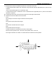
GENERAL INFORMATION 1–5 9. Measurement criteria are defined by the terms "standard" and "limit". A measurement falling within the "standard" range indicates that the applicable part or parts are serviceable. "Limit" should be thought of as an absolute value. A measurement which is outside the "limit" indicates that the applicable part or parts must be either repaired or replaced. 10. Components and parts are listed in the singular form throughout the Manual. 11.
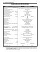
1–6 GENERAL INFORMATION MAIN DATA AND SPECIFICATIONS Engine Model Item Engine type AA-4BG1T BB-4BG1T Water cooled, four cycle, vertical in-line overhead valve Combustion chamber type Direct injection Cylinder liner type Dry No. of cylinders – bore × stroke Total piston displacement mm (in) 4 – 105 × 125 (4.13 × 4.92) L (cid) 4.329 (464) Compression ratio 18.0 to 1 * Engine dimensions Length × width × height 904 × 684.8 × 907 (35.6 × 27.0 × 35.
GENERAL INFORMATION 1–7 MAIN DATA AND SPECIFICATIONS Engine Model Item Engine type AA-6BG1 BB-6BG1T Water cooled, four cycle, vertical in-line overhead valve Combustion chamber type Direct injection Cylinder liner type Dry No. of cylinders - bore × stroke Total piston displacement 6 – 105.0 × 125.0 (4.13 × 4.92) mm (in) L (cid) 6.494 (396) Compression ratio 18.0 to 1 * Engine dimensions Length × width × height mm (in) * Engine weight (Dry) kg (lb) 1143 × 672 × 797 (45.0 × 26.5 × 31.
GENERAL INFORMATION 1–9 EXTERNAL VIEW MODEL AA-4BG1T, BB-4BG1T Turbocharger Turbocharger Oil filler cap Note: Engine details may vary depending on the specifications.
GENERAL INFORMATION 1–11 EXTERNAL VIEW MODEL BB-6BG1T Turbocharger Exhaust manifold Note: Engine details may vary depending on the specifications.
GENERAL INFORMATION 1–13 EXTERNAL VIEW MODEL AA-6BG1 Note: Engine details may vary depending on the specifications.
GENERAL INFORMATION 1–15 TIGHTENING TORQUE SPECIFICATIONS The tightening torque values given in the table below are applicable to the bolts unless otherwise specified. STANDARD BOLT N·m (kgf·m/lb.ft) Bolt Identification Bolt Diameter × pitch (mm) M 6 × 1.0 3.9–7.8 (0.4–0.8/2.9–5.8) 4.9–9.8 (0.5–1.0/3.6–7.2) M 8 × 1.25 7.8–17.7 (0.8–1.8/5.8–13.0) 11.8–22.6 (1.2–2.3/8.7–16.6) 16.7–30.4 (1.7–3.1/12.3–22.4) M10 × 1.25 20.6–34.3 (2.1–3.5/5.2–25.3) 27.5–46.1 (2.8–4.7/20.3–33.4) 37.3–62.8 (3.8–6.
1–16 GENERAL INFORMATION TIGHTENING TORQUE SPECIFICATIONS The tightening torque values given in the table below are applicable to the bolts unless otherwise specified. FLANGED HEAD BOLT N·m (kgf·m/lb.ft) Bolt Identification Bolt Diameter × pitch (mm) M 6 × 1.0 4.6–8.5 (0.5–0.9/3.6–6.5) 6.6–12.2 (0.6–1.2/4.3–8.7) M 8 × 1.25 10.5–196 (1.1–2.0/8.0–14.5) 15.3–28.4 (1.6–2.9/11.6–21.0) 18.1–33.6 (2.1–3.4/15.2–25.0) M10 × 1.25 23.1–38.5 (2.4–3.9/17.4–28.2) 35.4–58.9 (3.6–6.1/26.0–44.1) 42.3–70.5 (4.
GENERAL INFORMATION 1–17 ANGULAR NUT AND BOLT TIGHTENING METHOD 1. Carefully wash the nuts and bolts to remove all oil and grease. m nu e d de yb lfi e ol isu as M d re g 2. Apply a coat of molybdenum disulfide grease to the threads and setting faces of the nuts and bolts. 3. Tighten the nuts and bolts to the specified torque (snug torque) with a torque wrench. NUT OR BOLT Snug torque 4. Draw a line [A-B] across the center of each bolt.
1–18 GENERAL INFORMATION 5. Draw another line (C-D) on the face of each of the parts to be clamped. This line should be an extension of the line [A-B]. 6. Draw another line [F-G] on the face of each of the parts to be clamped. This line will be in the direction of the specified angle (Q) across the center [E] of the nut or bolt. 7. Use a socket wrench to tighten each nut or bolt to the point where the line [A-B] is aligned with the line [F-G].
GENERAL INFORMATION 1–19 MAJOR PART FIXING NUTS AND BOLTS Cylinder Head and Cover N·m (kgf·m/lb.ft) 6B 7.8–9.8 (0.8–1.0/5.8–7.2) 4B 5.9–16 (0.6–1.6/4.3–12) 69→88 →90°–120° (7.0/51)→(9.0/65) 42–62 (4.3–6.3/31–46) Apply MoS2 grease 20–25 (2.0–2.5/14–18) Glow plug 42–62 (4.3–6.3/31–46) Mos2 . . . . . . Molybdenum disulfide paste.
1–20 GENERAL INFORMATION Cylinder Body N·m (kgf·m/lb.ft) 42–62 (4.3–6.3/31–46) 21–30 (2.1–3.1/15–22) 21–30 (2.1–3.1/15–22) 21–30 (2.1–3.1/15–22) 226–245 (23–25/166–181) Apply engine oil 16–25 (1.6–2.
GENERAL INFORMATION 1–21 Oil Pan and Dipstick N·m (kgf·m/lb.ft) 25–30 (2.6–3.1/19–22) 21–30 (2.1–3.
1–22 GENERAL INFORMATION Camshaft and Rocker Arm 6B 25–35 (2.6–3.6/19–26) 4B 20–29 (2.0–3.0/15–22) N·m (kgf·m/lb.ft) 6B 25–35 (2.6–3.6/19–26) 4B 20–29 (2.0–3.0/15–22) 21–30 (2.1–3.1/15–22) 21–30 (2.1–3.1/15–22) 142–172 (14.5–17.5/105–127) Lubricate with engine oil 6B 44–64 (4.5–6.5/33–47) 4B 42–62 (4.3–6.
GENERAL INFORMATION 1–23 Crankshaft, Piston, and Flywheel N·m (kgf·m/lb.ft) 39 →60°–90° (4/29) Apply MoS2 grease 6B 4B 539–637 382–481 (55–65/378–470) (39–49/282–354) 6B 4B 197–240 142–172 (20.1–24.5/145–177) (14.5–17.
1–24 GENERAL INFORMATION Thermostat and Thermostat Housing 21–30 (2.1–3.1/15–22) 42–62 (4.3–6.3/31–46) 42–62 (4.3–6.3/31–46) N·m (kgf·m/lb.
GENERAL INFORMATION 1–25 Intake and Exhaust Manifold N·m (kgf·m/lb.ft) 21–30 (2.1–3.1/15–22) 6B 21–30 (2.1–3.1/15–22) 4B 14–24 (1.4–2.4/10–17) 6B 42–62 (4.3–6.3/31–46) 4B 22–31 (2.2–3.2/16–23) 6B 25–31 (2.6–3.2/19–23) 4B 16–25 (1.6–2.
1–26 GENERAL INFORMATION Timing Gear Case and Flywheel Housing N·m (kgf·m/lb.ft) 21–30 (2.1–3.1/15–22) 147–167 (15–17/108–123) 6B 21–30 (2.1–3.1/15–22) 4B 14–24 (1.4–2.4/10–17) Outer side 147–167 (15–17/108–123) 21–30 (2.1–3.
GENERAL INFORMATION 1–27 Oil Cooler, Oil Filter, and Oil Pump N·m (kgf·m/lb.ft) Refer to the section MAINTENANCE 4B 30–50 (3.1–5.1/22–37) 6B 42–62 (4.3–6.3/31–46) 42–62 (4.3–6.3/31–46) 21–30 (2.1–3.1/15–22) 6B 14–24 (1.4–2.4/10–17) 4B 16–25 (1.6–2.
1–28 GENERAL INFORMATION Fuel System N·m (kgf·m/lb.ft) 16–18 (1.6–1.8/12–13) 33–49 (3.4–5.0/25–36) 17–21 (1.7–2.1/12–15) 42–62 (4.3–6.3/31–46) 33–49 (3.4–5.0/25–36) 16–18 (1.6–1.8/12–13) 16–18 (1.6–1.8/12–13) 28–32 (2.9–3.3/21–24) 16–18 (1.6–1.8/12–13) 21–30 (2.1–3.1/15–22) 3.9–7.8 (0.4–0.8/2.9–5.
GENERAL INFORMATION 1–29 Turbocharger N·m (kgf·m/lb.ft) 16–25 (1.6–2.6/12–19) 28–46 (2.9–4.7/21–34) 16–25 (1.6–2.6/12–19) 6B 42–62 (4.3–6.3/31–46) 4B 22–31 (2.2–3.
1–30 GENERAL INFORMATION IDENTIFICATIONS 6B MODEL IDENTIFICATION Engine Serial Number The engine number is stamped on the front left hand side of the cylinder body. Engine serial number 4B INJECTION PUMP IDENTIFICATION Injection Pump Number Injection volume should be adjusted after referring to the adjustment data applicable to the injection pump installed. The injection pump identification number (A) is stamped on the injection pump identification plate.
MAINTENANCE 2–1 SECTION 2 MAINTENANCE TABLE OF CONTENTS ITEM PAGE Lubricating system . . . . . . . . . . . . . . . . . . . . . . . . . . . . . . . . . . . . . . . . . . . . . . . . . . . . . . . . . . . . . . . . . . . . . . . . . . . . . . . . . . . . . . . . 2– 2 Fuel system . . . . . . . . . . . . . . . . . . . . . . . . . . . . . . . . . . . . . . . . . . . . . . . . . . . . . . . . . . . . . . . . . . . . . . . . . . . . . . . . . . . . . . . . . . . . . . . . . 2– 3 Cooling system . . . . . . . .
2–2 MAINTENANCE LUBRICATING SYSTEM Main Oil Filter Replacement Cartridge (Spin-On) Type Removal Removal and Installer: Filter Wrench 1. Loosen the used oil filter by turning it counterclockwise with the filter wrench. 2. Discard the used oil filter. Installation 1. Wipe the oil filter mounting face with a clean rag. Set the filter wrench Cartridge This will allow the new oil filter to seat properly. 2. Lightly oil the O-ring. 3.
MAINTENANCE 2–3 FUEL SYSTEM Fuel Filter Replacement Cartridge (Spin-On) Type Removal 1. Loosen the fuel filter by turning it counterclockwise with the filter wrench or your hand. Discard the used filter. Filter Wrench 2. Wipe the fuel filter fitting face clean with a rag. This will allow the new fuel filter to seat properly.
2–4 MAINTENANCE Installation 1. Apply a light coat of engine oil to the O-ring. 2. Supply fuel to the new fuel filter. This will facilitate air bleeding. 3. Turn in the new fuel filter until the filter O-ring is fitted against the sealing face. 4. Use the filter wrench to turn in the fuel filter an additional 2/3 of a turn. Overflow Valve Check the overflow valve for clogging. Check the ball side for suction leakage kPa (kgf/cm2/psi) Overflow Valve Opening Pressure (Reference) 147 (1.
MAINTENANCE 2–5 MPa (kgf/cm2/psi) Injection Starting Pressure 1 18.1 (185/2630) WARNING TEST FLUID FROM THE NOZZLE TESTER WILL SPRAY OUT UNDER GREAT PRESSURE. IT CAN EASILY PUNCTURE A PERSON'S SKIN. KEEP YOUR HANDS AWAY FROM THE NOZZLE TESTER AT ALL TIMES. Spray Condition Check (During Injection Nozzle Tester Operation) (1) (2) (3) 1. Tighten the cap nut. 2. Check the injection nozzle starting pressure. 3. Check the injection nozzle spray condition.
2–6 MAINTENANCE Strainer Water Separator (Water Sedimentor) (Optional Equipment) Check the water separator float 1 level. If the float 1 has reached level 2, loosen the drain plug 3 (at the bottom side of the water separator) to drain the water. N·m (kgf·m/ft.lb) 2 1 Drain Plug Torque 3 9–15 (0.9–1.5/7–11) Air Bleeding 1. Loosen the feed pump cap 1 on the injection pump. 2. Loosen the fuel filter fuel return eye bolt 2. 3.
MAINTENANCE 2–7 Depress here 98N (10kgf/22lb) 2 COOLING SYSTEM Cooling Fan Drive Belt Adjustment 1. Check the cooling fan drive belt for cracking and other damage. 2. Check the drive belt tension by exerting a force of 98N (10kgf/22lb) midway between the fan pulley 2 and the alternator 3. 3. Adjust the belt tension by loosening the alternator mounting bolt and the alternator adjusting bolt and pivoting the alternator. Deflection 3 1 Be sure to retighten the bolts after adjusting the belt tension.
2–8 MAINTENANCE 2. Check to see if there is play in the No. 1 intake and exhaust valve rocker arms. 20 6 12 1. Bring the piston in either the No. 1 cylinder or the No. 6 cylinder to Top Dead Center on the compression stroke by turning the crankshaft until the TDC notched line on the crankshaft pulley is aligned with the timing pointer. If the No. 1 cylinder intake and exhaust valve rocker arms have play, the No. 1 piston is at TDC on the compression stroke. If the No.
MAINTENANCE 2–9 N·m (kgf·m/ft.lb) 6B Front Rocker Arm Screw Lock Nut Torque 21–30 (2.1–3.1/15–22) When No.6 cylinder at TDC compression stroke 4B Front Note: The valve clearance adjustment procedure for the 4BG1 engines is identical to that for the 6BG1 engines. Only the number of cylinders is different. When No. 1 cylinder is at TDC in compression stroke Front 4B When No.
2–10 MAINTENANCE Checking Procedure 1. Align the crankshaft pulley TDC mark with the pointer. 20 6 12 Remove the inspection hole cover at the front of the injection pump on the timing gear case cover. Check the alignment between the pointer 4 on the injection pump gear nut lock plate and the projection area mark 3 on the injection pump gear case. If it is in misalignment, recheck with turning the crankshaft pulley one more turn to repeat the aforegoing procedure to mark sure that it is in alignment.
MAINTENANCE 2–11 6. Hold the fuel control lever at the fully open position. 7. Slowly turn the crankshaft pulley clockwise, at the same time, continue to feed the fuel with pumping the priming pump. When the fuel stop to flow out from the No. 1 delivery valve holder, stop the pump instantaneously. This crankangle position is the injection starting of the engine. 8. Observe and make sure that mark (injection starting angle line a°) on the crankshaft pulley is aligning with the pointer.
2–12 MAINTENANCE Note: Injection pump injection timing will vary among identical engines contact your machine supplier or nearest ISUZU engine service outlet for the specifications applicable to your engine. These specifications have been set by ISUZU and the OEM manufacturer. Holder 9. Remove the delivery valve holder from the No. 1 plunger. 10. Reinstall the delivery valve internal parts (seat, spring, and valve) to the delivery valve holder. Seat Spring 11.
MAINTENANCE 2–13 5. Do a fine injection pump position adjustment, while continue the pumping operation to feed the fuel, and stop to pivot the injection pump when the fuel stop to flow out from the No. 1 delivery valve holder. 6. Tighten the four injection pump fixing nuts. 7. Once remove the No. 1 delivery valve holder, and reinstall the delivery valve, spring and the valve holder with the specified torque. 8. Install the No. 1 injection pipe and tighten it to the specified torque.
2–14 MAINTENANCE 3. Perform the operations described on page 2-10, 11 paragraphs 3, 4, 5, 6. 4. Slowly turn the coupling counterclockwise (viewed from the timing gear case). At the same time, operate the priming pump to feed fuel to the No. 1 injection pump plunger. Visually check that fuel is being fed (from the top of the delivery valve holder). 5. Continue to operate the priming pump. Turn the coupling counterclockwise until the fuel stops flowing from the delivery valve holder.
MAINTENANCE 2–15 COMPRESSION PRESSURE MEASUREMENT 1. Operate the engine to warm-up until the coolant temperature reaches to 75°C (167°F). 2. Remove all of the glow plugs and the injection pipes. 3. Attach a compression gauge to the No. 1 cylinder glow plug installation threads. Note: Compression gauge adaptor Compression pressure may be measured starting at any cylinder and in no particular cylinder order. However, it is very important that the compression pressure be measured in each cylinder.
2–16 MAINTENANCE TURBOCHARGER INSPECTION 1. Check the air intake duct connections for air leakage. 2. Check the air duct connections for air leakage. 3. Check the exhaust duct connections for smoke leakage. 4. Check the turbocharger mounting nuts for looseness. 5. Check the oil feed pipe for oil leakage. 6. Check the oil return pipe joints for oil leakage.
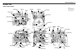
MAINTENANCE 2–17 ENGINE REPAIR KIT (FOR NATURALLY ASPIRATED ENGINES) 15 29 20 13 28 25 19 8 14 26 27 18 26 VIEW “A” 24 30 3 25 2 1 4 10 5 A 6 7 21 22 16 17 9 25 26 23 1. 2. 3. 4. 5. 6. 7. 8. 9. 10. 11. 12. 13. 14. 15.
2–18 MAINTENANCE ENGINE REPAIR KIT (FOR TURBOCHARGED ENGINES) 18 23 7 21 16 11 6 27 35 34 33 22 21 17 VIEW (A) 3 33 2 1 26 28 25 31 12 36 A 4 24 8 10 15 29 5 19 9 23 31 13 20 15 14 32 1. 2. 3. 4. 5. 6. 7. 8. 9. 10. 11. 12. 13. 14. 15. 16. 17. 18.
MAINTENANCE 2–19 RECOMMENDED LUBRICANTS ENGINE TYPE TYPES OF LUBRICANTS (API) Without turbocharger & With turbocharger Diesel engine oil CD grade ENGINE OIL VISCOSITY CHART ENGINE OIL VISCOSITY GRADE – AMBIENT TEMPERATURE [Single grade] ;;;;;;;;;;;;;;;;;;;;;;;;;;;;;;;;;;;;;;;; ;;;;;;;;;;;;;;;;;;;;;;;;;;;;;;;;;;;;;;;; ;;;;;;;;;;;;;;;;;;;;;;;;;;;;;;;;;;;;;;;; SAE 20, 20W ;;;;;;;;;;;;;;;;;;;;;;;;;;;;;;;;;;;;;;;; ;;;;;;;;;;;;;;;;;;;;;;;;;;;;;;;;;;;;;;;; ;;;;;;;;;;;;;;;;;;;; ;;;;;;;;;;;;;;;;;;;; ;;;;;;;;;
MEMO
ENGINE ASSEMBLY I 3–1 SECTION 3 ENGINE ASSEMBLY I (DISASSEMBLY) TABLE OF CONTENTS ITEM PAGE External parts disassembly steps. . . . . . . . . . . . . . . . . . . . . . . . . . . . . . . . . . . . . . . . . . . . . . . . . . . . . . . . . . . . . . . . . . . . . . . . 3– 2 Major components. . . . . . . . . . . . . . . . . . . . . . . . . . . . . . . . . . . . . . . . . . . . . . . . . . . . . . . . . . . . . . . . . . . . . . . . . . . . . . . . . . . . . . . . .
3–2 ENGINE ASSEMBLY I EXTERNAL PARTS DISASSEMBLY STEPS (Right-hand side) MODEL BB-6BG1T 4 9 5 8 14 6 1 16 7 12 2 13 15 10 Disassembly Steps 1. 2. 3. 4. 5. 6. Fan guide Cooling fan Not installed Intake pipe Fuel return pipe Fuel pipe; fuel filter to injection pump 7. Fuel pipe; feed pump to filter 8. Injection pipe and leak off pipe 9. Injection nozzle 10. Oil pipe; injection pump to cylinder body 11. Not installed 12. Oil pipe; filter to oil cooler ▲ 13.
ENGINE ASSEMBLY I 3–3 MODEL BB-4BG1T 3 7 4 8 5 13 15 11 6 1 9 12 14 Disassembly Steps 1. 2. 3. 4. 5. Cooling fan Not installed Intake pipe Fuel return pipe Fuel pipe; fuel filter to injection pump 6. Fuel pipe; feed pump to filter 7. Injection pipe and leak off pipe 8. Injection nozzle 9. Oil pipe; injection pump to cylinder body 10. Not installed 11. Oil pipe; filter to oil cooler ▲ 12. Injection pump with injection pump gear 13. Fuel filter 14. Oil filter 15.
3–4 ENGINE ASSEMBLY I Important Operations 12. Injection Pump with Injection Pump Gear Use the shipping plugs (or something similar) to seal the injection pump delivery valve ports. This will prevent the entry of foreign material. Flange Mounted Injection Pump Removal 1) Remove the injection pump flange bolts. 2) Pull the injection pump with the injection pump drive gear free. Refer to the illustration. Coupling Mounted Injection Pump Removal 1) Remove the two coupling bolts to disconnect the coupling.
ENGINE ASSEMBLY I 3–5 EXTERNAL PARTS DISASSEMBLY STEPS (Left-hand side) MODEL BB-6BG1T 5 6 1 11 2 10 8 9 3 7 4 Disassembly Steps 1. 2. 3. 4. ▲ 5. Dipstick and guide tube Air breather Oil feed pipe Oil drain pipe Turbocharger 6. 7. 8. 9. 10. 11.
3–6 ENGINE ASSEMBLY I MODEL BB-4BG1T 1 6 2 7 12 10 4 11 8 9 5 Disassembly Steps 1. 2. 3. 4. 5. ▲ 6. Dipstick and guide tube Air breather (Not installed) Oil feed pipe Oil drain pipe Turbocharger 7. 8. 9. 10. 11. 12. Gasket Starter Fan belt Alternator Fan pulley Cylinder head cover Important Operations 6. Turbocharger Plug oil ports in turbocharger body immediately after removal of the turbocharger.
ENGINE ASSEMBLY I 3–7 MAJOR COMPONENTS - I 2 3 4 5 9 1 7 6 16 12 10 15 14 11 8 13 : Repair kit Disassembly Steps 1. ▲ 2. 3. ▲ 4. 5. 6. 7. 8. Rubber hose ; water by-pass Rocker arm shaft assembly Push rod Cylinder head bolt Cylinder head assembly Cylinder head gasket Water pump assembly Tappet chamber cover 9. ▲ 10. ▲ 11. 12. 13. 14. ▲ 15. ▲ 16.
3–8 ENGINE ASSEMBLY I 6B series Important Operations 2. 1 4 8 3 7 12 13 9 11 14 10 Rocker Arm Shaft Loosen the rocker arm shaft fixing bolts a little at a time in numerical sequence as specified. 5 2 6 4B series 9 5 1 4 6 8 2 7 3 Front 4. 6B series Cylinder Head Bolts Loosen the cylinder head bolts a little at a time in the numerical order shown in the illustration.
ENGINE ASSEMBLY I 3–9 Taper bushing 11. Taper Bushing (6B series only) Remover: 9-8521-0122-0 Use the taper bushing remover to remove the crankshaft end taper bushing. Crankshaft Pulley Taper bushing remover 15. Flywheel Loosen the flywheel bolt a little at a time in the numerical order as specified. 3 1 6 5 2 4 16. Crankshaft Rear Oil Seal (Axial Type) With the oil seal pushed in deep, install the special tool as shown in the illustration and remove the oil seal.
3–10 ENGINE ASSEMBLY I MAJOR COMPONENTS - II 2 11 13 12 3 14 15 5 16 8 4 7 1 10 9 6 : Repair kit Disassembly Steps 1. 2. 3. 4. 5. ▲ 6. ▲ 7. 8. Oil cooler Oil pan Oil pump and coupling Flywheel housing Piston and connecting rod Idler gear Camshaft Tappet 9. 10. ▲ 11. 12. 13. 14. 15. 16.
ENGINE ASSEMBLY I 3–11 Important Operations 6. Idler Gear Measure the following points before disassembly. mm (in) Idler Gear End Play Feeler gauge Standard Limit 0.128–0.185 (0.005–0.0070) 0.2 (0.008) mm (in) Timing Gears Backlash Standard Limit 0.10–0.17 (0.004–0.007) 0.3 (0.012) Includes the crankshaft gear, the camshaft gear, and the idler gear. Dial indicator Crankshaft gear 7 Camshaft Measure the following points before disassembly.
3–12 ENGINE ASSEMBLY I ROCKER ARM, AND ROCKER ARM SHAFT DISASSEMBLY STEPS 4 3 2 1 Disassembly Steps 1. Bracket 2. Rocker arm 3. Spring 4.
ENGINE ASSEMBLY I 3–13 CYLINDER HEAD DISASSEMBLY STEPS 6 7 8 9 2 11 3 4 5 1 10 : Repair kit Disassembly Steps 1. 2. 3. 4. 5. ▲ 6. Exhaust manifold and gasket Intake manifold and gasket Water outlet pipe Thermostat Thermostat housing and gasket Split collar 7. Spring seat (upper) or *Valve rotator (if so equipped) 8. Valve spring 9. Spring seat (lower) 10. Valve 11. Valve stem oil seal * The valve rotator is used for 6BB1 and 6BD1/6BD1T engines only. Important Operation 6.
3–14 ENGINE ASSEMBLY I PISTON AND CONNECTING ROD DISASSEMBLY STEPS 1 4 2 3 2 3 5 Disassembly Steps ▲ 1. Piston rings ▲ 2. Snap ring ▲ 3. Piston pin and connecting rod 4. Piston 5.
ENGINE ASSEMBLY I 3–15 Important Operation Note: Carbon deposits Remove any carbon deposits from the upper part of the cylinder bore. This will prevent damage to the piston and the piston rings when they are removed from the cylinder bore. Piston ring remover 1. Piston Rings Use a piston ring remover to remove the piston rings. Do not attempt to use some other tool. Piston ring stretching will result in reduced piston ring tension. Piston ring remover: 2, 3.
MEMO
ENGINE ASSEMBLY II 4–1 SECTION 4 ENGINE ASSEMBLY II (INSPECTION & REPAIR) TABLE OF CONTENTS ITEM PAGE Cylinder head . . . . . . . . . . . . . . . . . . . . . . . . . . . . . . . . . . . . . . . . . . . . . . . . . . . . . . . . . . . . . . . . . . . . . . . . . . . . . . . . . . . . . . . . . . . . . . . 4– 2 Valve guide. . . . . . . . . . . . . . . . . . . . . . . . . . . . . . . . . . . . . . . . . . . . . . . . . . . . . . . . . . . . . . . . . . . . . . . . . . . . . . . . . . . . . . . . . . . . .
4–2 ENGINE ASSEMBLY II INSPECTION AND REPAIR Make the necessary adjustments, repairs, and part replacements if excessive wear or damage is discovered during inspection. CYLINDER HEAD Cylinder Head Lower Face Warpage 1. Use a straight edge and a feeler gauge to measure the four sides and the two diagonals of the cylinder head lower face. 2. Regrind the cylinder head lower face if the measured values are greater than the specified limit but less than the maximum grinding allowance.
ENGINE ASSEMBLY II 4–3 VALVE GUIDE Valve Stem and Valve Guide Clearance Measuring Method - 1 1. With the valve stem inserted in the valve guide, set the dial indicator needle to "0". 2. Move the valve head from side to side Note the total dial indicator reading (TIR). This value is the clearance between the valve stem and the valve guide. If the measured values exceed the specified limit, the valve and the valve guide must be replaced as a set.
4–4 ENGINE ASSEMBLY II Valve Depression 2 1. Install the valve 1 to the cylinder head 2. 2. Use a depth gauge or a straight edge with steel rule to measure the valve depression from the cylinder head lower surface. If the measured value exceeds the specified limit, the valve seat insert and/or valve must be replaced. 1 If the valve is replaced, the valve guide must be also replaced. mm (in) Intake and Exhaust Valve Depression Standard Limit 1.0 (0.039) 2.5 (0.098) Valve Contact Width 1.
ENGINE ASSEMBLY II 4–5 3. Use a screwdriver 3 to pry the valve seat insert free. Take care not to damage the cylinder head 4. 4. Carefully remove carbon and other foreign material from the cylinder head insert bore. Valve Seat Installation 3 1 1. Carefully place the attachment 1 (having the smaller outside diameter than the valve seat insert) on the valve seat insert 2. Note: 2 The smooth side of the attachment must contact the valve seat insert. 2.
4–6 ENGINE ASSEMBLY II Angle Location Standard Intake Valve Seat Angle B 45° Exhaust Valve Seat Angle B 45° Note: Use an adjustable valve cutter pilot. Do not allow the cutter pilot to wobble inside the valve guide. 3. Apply abrasive compound to the valve seat insert surface. 4. Insert the valve into the valve guide. 5. Hand lap the valve and the valve seat with a lapping cup. This will provide optimum valve and valve seat contact for effective gas sealing. B 6.
ENGINE ASSEMBLY II 4–7 Valve Spring Inclination Use a surface plate and a square to measure the valve spring inclination. If the measured value exceeds the specified limit, the valve spring must be replaced. mm (in) Valve Spring Inclination Standard Limit less than 1.9 (0.075) 2.7 (0.106) Valve Spring Tension Use a spring tester to measure the valve spring tension. If the measured value is less than the specified limit, the valve spring must be replaced. N (kg/lb) Set Length Standard Limit 44.
4–8 ENGINE ASSEMBLY II Use a dial indicator to measure the clearance between the tappet and cylinder body tappet travelling bore. mm (in) Tappet and Tappet Travelling Bore Clearance Standard Limit 0.020–0.054 (0.001–0.002) 0.1 (0.004) PUSH ROD Use a filler gauge to measure the valve push rod run out. Roll the push rod along a smooth flat surface (illustration). mm (in) Limit Push Rod Run-Out 2 1 0.3 (0.
ENGINE ASSEMBLY II 4–9 Rocker Arm Shaft and Rocker Arm Clearance 1. Use a vernier caliper to measure the rocker arm bushing inside diameter. mm (in) Rocker Arm Bushing Inside Diameter Standard Limit 19.01–19.03 (0.749–0.750) 19.05 (0.751) 2. Measure the rocker arm shaft outside diameter. Replace either the rocker arm or the rocker arm shaft if the clearance exceeds the specified limit. mm (in) Standard Rocker Arm Bushing 0.01–0.05 and Rocker Arm (0.0004–0.0020) Shaft Clearance Limit 0.2 (0.0079) 3.
4–10 ENGINE ASSEMBLY II 2. Use a dial indicator to measure the idler gear inside diameter. mm (in) Idler Gear and Idler Gear Shaft Clearance Standard Limit 0.025–0.085 (0.001–0.003) 0.2 (0.008) CAMSHAFT 1. Use the camshaft bearing remover and installer to remove camshaft bearing from the cylinder body. Camshaft Bearing Remover and Installer: 9-85231818-0 2. Measure the clearance between the cam journal and the camshaft bearing.
ENGINE ASSEMBLY II 4–11 5. Place the camshaft on a measuring stand. Use a dial indicator to measure the camshaft runout. Note the total indicator reading (TIR). If the measured run-out exceeds the specified limit, the camshaft must be replaced. mm (in) Limit Camshaft Run-Out TIR 0.12 (0.005) CYLINDER BODY AND LINER Cylinder Liner Bore Measurement 3 1 Use a cylinder indicator to measure the cylinder liner bore at measuring position 1 in line with the crankshaft 2 and across the crankshaft 3.
4–12 ENGINE ASSEMBLY II Cylinder Liner Projection Inspection 1 1. Hold a straight edge 1 along the top edge of the cylinder liner to be measured. 2. Use a feeler gauge 2 to measure each cylinder liner projection. mm (in) 2 Standard Cylinder Liner Projection 0.03–0.10 (0.001–0.004) The difference in the cylinder liner projection height between any two adjacent cylinders must not exceed 0.03 mm (0.001 in). Cylinder Liner Replacement Cylinder Liner Removal Remover 1.
ENGINE ASSEMBLY II 4–13 Cylinder Bore Measurement Cylinder Liner Grade Selection The term "grade" refers to the cylinder body inside diameter and the cylinder liner outside diameter combination. Measure the cylinder body inside diameter and select the appropriate cylinder liner grade. Loose fitting cylinder liners (the liner is too small for the cylinder bore) will adversely affect engine cooling efficiency and may lead to serious engine damage.
4–14 ENGINE ASSEMBLY II Cylinder Liner Outside Diameter Measurement X 1 Y 1. Take measurements at measuring point 1, 2, and 3. Y X 2 Measuring Points mm (in): X Y 3 Y X 2 105.0 (4.137) X 3 195.0 (7.683) Y Y X 1 20.0 (0.788) 2. Calculate the average value of the 6 measurements to determine the correct cylinder liner grade. mm (in) Cylinder Liner Fitting Clearance Standard 0.001–0.019 (0.00004–0.
ENGINE ASSEMBLY II 4–15 Cylinder Liner Installation 1. Carefully wipe away any foreign material from the cylinder liner inside and outside surfaces and the cylinder bore. 2. Use new kerosene or diesel oil to thoroughly clean the cylinder liner and bore surfaces. 3. Use a clean rag to remove all traces of kerosene or diesel oil from the cylinder liner and bore surfaces. 4. Insert the cylinder liner 1 into the cylinder body 2 from the top of the cylinder body. 3 5.
4–16 ENGINE ASSEMBLY II Cylinder Liner Bore Measurement 1. Locate the two measuring points. Cylinder Liner Measuring Point 1: 20 mm (0.788 in) Cylinder Liner Measuring Point 2: 105 mm (4.173 in) 2. Measure the cylinder liner bore at measuring point 1 and 2 in four different directions (W–W, X–X, Y–Y, and Z–Z). 3. Calculate the average value of the eight measurements. mm (in) Cylinder Liner Bore Total Indicator Reading 105.021–105.060 (4.1347–4.
ENGINE ASSEMBLY II 4–17 Piston Outside Diameter Measure the piston outside diameter at the measuring piston shown in the illustration. Piston Grade (For service parts) mm (in) AX CX 104.959–104.974 (4.1322–4.1328) 104.975–104.990 (4.1329–4.1335) 82 Cylinder Liner Bore and Piston Clearance (For service parts) mm (in) Cylinder Liner Bore and Piston Clearance 0.051–0.085 (0.002–0.0033) Piston Selection Select the same grade number as the one for the cylinder liner inside dia meter.
4–18 ENGINE ASSEMBLY II Piston Ring Gap 1 2 1. Insert the piston ring horizontally (in the position it would assume if it were installed to the piston) into the cylinder liner. 2. Use an inverted piston to push the piston ring into the cylinder liner until it reaches either measuring point 1 or measuring point 2. Cylinder liner diameter is the smallest at these two points. Do not allow the piston ring to slant to one side or the other. It must be perfectly horizontal.
ENGINE ASSEMBLY II 4–19 PISTON PIN Piston Pin Outside Diameter Use a micrometer to measure the piston pin outside diameter at several points. If the measured piston pin outside diameter exceeds the specified limit, the piston pin must be replace. mm (in) Piston Pin Outside Diameter Standard Limit 35.000–35.005 (1.3780–1.3781) 34.95 (1.3760) Piston Pin and Piston Clearance Use an inside dial indicator to measure the piston pin hole. mm (in) Piston Pin Hole Diameter 4BG1, 4BG1T, 6BG1 6BG1T Standard 35.
4–20 ENGINE ASSEMBLY II CONNECTING ROD Connecting Rod Alignment Use a connecting rod aligner to measure the connecting rod’s twist distortion and parralelism between the rod’s large and small ends. If the measured value exceeds the limit, replace the connecting rod. Connecting Rod Alignment (Per Length of 100 mm (3.94 in) Twist, Parallelism mm (in) Standard Limit 0.05 (0.002) or less 0.20 (0.
ENGINE ASSEMBLY II 4–21 Connecting Rod Bushing Installation Use the connecting rod bushing installer to install the connecting rod bushing. Connecting Rod Bushing Installer: 9-8523-1369-0 (J-29765) Note: The connecting rod bushing oil port must be aligned with the connecting rod oil port. 3. Use a piston pin hole grinder 1 fitted with a reamer 2 or an adjustable pilot reamer to ream the piston pin hole. mm (in) 1 Standard Connecting Rod Bushing Inside Diameter 35.017–35.025 (1.3786–1.
4–22 ENGINE ASSEMBLY II CRANKSHAFT Crankshaft and Bearing Inspection 1. Inspect the crankshaft journal surfaces and the crank pin surfaces for excessive wear and damage. 2. Inspect the oil seal fitting surfaces of the crankshaft front and rear ends for excessive wear and damage. 3. Replace or repair the crankshaft if any excessive wear or damage is discovered. 4. Inspect the crankshaft oil ports for obstructions. 5. Use high pressure air to clean the oil ports if necessary.
ENGINE ASSEMBLY II 4–23 mm (in) Standard Crankshaft Pin Diameter 63.924–63.944 (2.5167–2.5175) 4. Measure the crankshaft journal outside diameter (and/or the crankpin outside diameter) and the bearing inside diameters to determine the bearing clearance. Crankshaft Journal and Bearing Clearances If the bearing clearance exceeds the specified limit, the crankshaft must be reground (except 4BD1T, 6BD1T, 6BG1 and 6BG1T) and/or the bearing must be replaced.
4–24 ENGINE ASSEMBLY II Crankshaft Journal Bearing Inside Diameter 1. Install the main bearing cap with bearings to the cylinder body with the specified torque and facing the arrow mark on the bearing cap toward front. Place them in order of punched cylinder numbers. 2. Use an inside dial indicator to measure the main bearing diameters. N·m (kgf·m/ft.lb) Main Bearing Cap Torque 226 – 245 (23 – 25/166 – 181) mm (in) Main Bearing Nominal Diameter 80 (3.
ENGINE ASSEMBLY II 4–25 Crankshaft Run-Out 1. Mount the crankshaft on a set of V-blocks. 2. Set a dial indicator to the center of the crankshaft journal. 3. Gently turn the crankshaft in the normal direction of engine rotation. Read the dial indicator (TIR) as you turn the crankshaft. If the measured value exceeds the specified limit, the crankshaft must be replaced. mm (in) Crankshaft Run-Out Model Standard Limit 6B 0.05 (0.002) or less 0.40 (0.
4–26 ENGINE ASSEMBLY II Plastigage Clearance Measurements This is another method to measure the crankjournal bearing clearance. Crankshaft Journal Bearing Clearance 1. Clean the cylinder body, the journal bearing fitting portions, the bearing cap, and the inside the outside surfaces of the bearing. 2. Install the new journal bearing to the cylinder body. 3. Carefully place the crankshaft on the bearing. 4. Rotate the crankshaft approximately 30° to seat the bearing. 5.
ENGINE ASSEMBLY II 4–27 Crankshaft Pin Bearing Clearance 1. Clean the crankshaft, the connecting rod, the bearing cap, and the bearings. 2. Install the bearing to the connecting rod. Do not allow the crankshaft to move when installing the bearing cap. 3. Hold the connecting rod (with the bearing installed) against the crankshaft pin. 4. Attach the plastigage to the crankshaft pin. Apply engine oil to the plastigage to keep it from falling. 5.
4–28 ENGINE ASSEMBLY II Judgement 1. Wait for thirty to forty seconds. If there is no discoloration after thirty or forty seconds, the crankshaft is usable. If discoloration appears (the surface being tested will become the color of copper), the crankshaft must be replaced. 2. Clean the surface being tested with clean water of steam immediately after completing the test. Note: The ammonium cuprous chloride solution is highly corrosive.
ENGINE ASSEMBLY II 4–29 Crankshaft Gear Replacement Remover Removal Use the crankshaft gear remover to remove the crankshaft gear. Crankshaft Gear Remover: 9-8521-0141-0 Installation Use the crankshaft gear installer to install the crankshaft gear. Crankshaft Gear Installer: 9-8522-0033-0 Installer FLYWHEEL AND FLYWHEEL HOUSING Ring Gear Inspection Inspect the ring gear. If the ring gear teeth are broken or excessively worn, the ring gear must be replaced.
MEMO
ENGINE ASSEMBLY III 5–1 SECTION 5 ENGINE ASSEMBLY III (REASSEMBLY) TABLE OF CONTENTS ITEM PAGE Piston and connecting rod reassembly steps. . . . . . . . . . . . . . . . . . . . . . . . . . . . . . . . . . . . . . . . . . . . . . . . . . . . . . . . . . 5– 2 Cylinder head reassembly steps . . . . . . . . . . . . . . . . . . . . . . . . . . . . . . . . . . . . . . . . . . . . . . . . . . . . . . . . . . . . . . . . . . . . . . . . . 5– 4 Rocker arm and rocker arm shaft reassembly steps. . . . . . . . . .
5–2 ENGINE ASSEMBLY III PISTON AND CONNECTING ROD REASSEMBLY STEPS MIRROR COMPONENT 4 1 3 3 3 2 5 Reassembly Steps ▲ 1. ▲ 2. ▲ 3. Piston Connecting-rod Piston pin, Snap ring ▲ 4. ▲ 5.
ENGINE ASSEMBLY III 5–3 PISTON AND CONNECTING ROD Conventional piston heater Important Operations 1. Piston Use a piston heater to heat the pistons to approximately 60°C (140°F). 2. Connecting Rod 1) Install the connecting rod to the piston with setting the marks as illustrated. 2) Install the piston pin into the piston and the connecting rod bushing. Piston head Refer the description of piston pin in page 4-19. 3.
5–4 ENGINE ASSEMBLY III CYLINDER HEAD REASSEMBLY STEPS 6 5 4 3 10 1 9 8 7 11 2 : Repair kit Reassembly Steps ▲ 1. Valve stem oil seal ▲ 2. Intake and exhaust valves 3. Spring seat (Lower) ▲ 4. Intake and exhaust valve springs 5. Spring seat (Upper) or valve rotator ▲ 6. Spring seat split collar 7. 8. 9. ▲ 10. ▲ 11.
ENGINE ASSEMBLY III 5–5 Important Operations Installer 1. Valve Stem Oil Seal 1) Lubricate the oil seals and valve stem sealing areas with engine oil. 2) Use a valve stem oil seal installer to install the oil seal. Valve Stem Oil Seal Installer: 1-85221-005-0 2. Intake and Exhaust Valves 1) Place the cylinder head on a flat wooden surface. 2) Lubricate valve stems with engine oil. 3) Install the valves to the intake or exhaust guides. Install the valves to their original lapped valve seats. 4.
5–6 ENGINE ASSEMBLY III 10. Intake Manifold and Gasket 1) Install the intake manifold gasket. Unchamfered corner The intake manifold gasket must be installed with its unchamfered corner facing up and to the front of the engine. Refer to the illustration. 2) Install the intake manifold. Rear 3) Tighten the intake manifold bolts to the specified torque a little at a time in the numerical order shown in the illustration. N·m (kgf·m/lb.ft) 12 Intake Monifold Bolt Torque 8 4 5 1 10 6 4B 14–24 (1.4–2.
ENGINE ASSEMBLY III 5–7 4BG1 6 5 2 1 7 3 4 8 4) Install either end of the distance tube to the spot facing (6B series engine only).
5–8 ENGINE ASSEMBLY III ROCKER ARM AND ROCKER ARM SHAFT REASSEMBLY STEPS 1 2 3 4 Reassembly Steps ▲ 1. Rocker arm shaft 2. Spring 3. Rocker arm 4. Bracket Important Operation 1. Rocker Arm Shaft The rocker arm shaft must be installed with the oil ports facing up.
ENGINE ASSEMBLY III 5–9 MAJOR COMPONENT REASSEMBLY STEPS I 15 4 5 12 3 14 2 11 1 *7 13 8 16 9 6 10 : Repair kit Reassembly Steps ▲ 1. Oil jet ▲ 2. Crankshaft bearing (upper half) 3. Crankshaft ▲ 4. Thrust bearing ▲ 5. Crankshaft bearing (lower half) and crankshaft bearing cap ▲ 6. Timing gear case * 7. Tappet ▲ 8. Camshaft ▲ 9. ▲ 10. ▲ 11. ▲ 12. ▲ 13. ▲ 14. ▲ 15. ▲ 16.
5–10 ENGINE ASSEMBLY III Important Operations 1. Oil Jet Install the oil jets taking care not to damage the oil jet nozzles. N·m (kgf·m/lb.ft) Fit correctly With oil hole and groove (upper) Oil Jet Torque 16–25 (1.6–2.6/12–19) 2. Crankshaft Bearing (Upper Half) 5.
ENGINE ASSEMBLY III 5–11 N·m (kgf·m/lb.ft) 11 7 3 1 5 9 13 12 8 4 2 6 10 14 Crankshaft Bearing Cap Bolt Torque 226–245 (23.0–25.0/166–181) 4) Check that the crankshaft turns smoothly by manually rotating it. Lubricate with engine oil 6. Timing Gear Case 1) Apply liquid gasket to the timing gear case surfaces contacting the cylinder body. 2) Tighten the timing gear case bolts to the specified torque. N·m (kgf·m/lb.ft) Timing Gear Case Bolt Torque 21–30 (2.1–3.1/15–22) 8.
5–12 ENGINE ASSEMBLY III 11. Piston and Connecting Rod 3 2 Position the piston ring gaps as shown in the illustration. 1) Set the piston ring gaps as shown in the illustration. 2) Lubricate the piston, the piston rings, and the connecting rod bearings with engine oil. 3) Position the piston front mark towards the front of the engine. 1 4 4) Use the piston ring compressor to compress the piston rings.
ENGINE ASSEMBLY III 5–13 13. Flywheel Housing 1) Apply a sealant to the shaded area of the illustration. 2) Install the flywheel housing. Tighten the flywheel housing bolts to the specified torque. N·m (kgf·m/lb.ft) Flywheel Housing Bolt Torque Outer Bolt 147–167(15.0–17.0/108–123) Inner Bolt 21–30 (2.1–3.1/15–22) 14. Rear Oil Seal (Axial Type) 11.6 0.3mm (0.457 1) Tighten the adapter to the crankshaft rear and section with 2 bolts. 2) Insert the oil seal into the peripheral section of adapter.
5–14 ENGINE ASSEMBLY III MAJOR COMPONENT REASSEMBLY STEPS II 15 14 13 12 2 8 16 10 11 1 5 3 76 9 4 : Repair kit Reassembly Steps ▲ 1. Flywheel ▲ 2. Injection pump and injection pump gear 3. Oil thrower 4. Timing gear cover 5. Crankshaft pulley and dust thrower 6. Taper bushing ▲ 7. Crankshaft pulley nut 8. Oil pump driving pinion ▲ 9. ▲ 10. ▲ 11. ▲ 12. ▲ 13. 14. ▲ 15. 16.
ENGINE ASSEMBLY III 5–15 Important Operations 1. Flywheel 1) Lubricate the flywheel bolt threads. 31 6 5 2 4 2) Install the flywheel. The crankshaft rear end dowel pin and the flywheel dowel hole must be aligned. Lubricate with engine oil 3) Tighten the flywheel bolts to the specified torque in the numerical order shown in the illustration. N·m (kgf·m/lb.ft) Flywheel Bolt Torque 4B engine 142–172(14.5–17.5/105–127) 6B engine 197–240(20.1–24.5/145–177) 2.
5–16 ENGINE ASSEMBLY III 2. Install the air compressor 3. Tighten the air compressor mounting bolts. Mark After installing the air compressor, perform Step 3 of "Injection Pump and Injection Pump Gear Assembly" (on the following page). Refer to injection timing in section MAINTENANCE to check the injection timing for correctness. Pulley 7. Crankshaft Pulley Nut 1) Apply MoS2 to the crankshaft pulley nut threads and fitting face.
ENGINE ASSEMBLY III 5–17 3) Carefully place the cylinder head on the cylinder body. 6B series 4) Tighten the cylinder head bolt as follows. 19 12 20 Front 21 11 4 13 22 14 18 10 3 2 9 17 8 1 5 25 16 7 6 26 24 23 15 1) As cylinder head bolts have two kinds of length, install them at proper location. The shorter ones (4B series; 4 bolts, 6B series; 6 bolts) must be used at the injection pump side. 2) Follow the numerical sequence shown in the illustrations.
5–18 ENGINE ASSEMBLY III 15. Rocker Arm and Rocker Arm Shaft 1) Check that the rocker arm shaft bracket lower surface oil port is free from obstruction. 13 9 5 1 4 10 6 2 3 8 7 12 14 2) Install the rocker arm shaft with the bracket to the cylinder head. 11 3) Tighten the rocker arm bracket bolts to the specified torque a little at a time in the numerical order shown in the illustration. 4) Lubricate the rocker arm and the rocker arm shaft with engine oil. N·m (kgf·m/lb.ft) 6B 25–35 (2.6–3.
ENGINE ASSEMBLY III 5–19 EXTERNAL PARTS REASSEMBLY STEPS (Left-hand side) 7 11 6 1 10 4 2 3 5 9 8 Reassembly Steps ▲ 1. 2. 3. ▲ 4. ▲ 5. ▲ 6. Cylinder head cover Fan pulley Alternator Fan belt Starter Turbocharger mounting flange gasket. ▲ 7. Turbocharger ▲ 8. Oil drain pipe ▲ 9. Oil feed pipe 10. Air breather 11.
5–20 ENGINE ASSEMBLY III 6B series Important Operations 1. Cylinder Head Cover 3 1 4 2 1) Check that the rocker arms, the rocker arm shafts, and the valve springs are thoroughly lubricated with engine oil. If required, relubricate these parts. 2) Place the cylinder head cover gasket on the cylinder head cover. Check the head cover gasket for looseness. 4B series 3 1 2 3) Tighten the cylinder head cover bolts to the specified torque a little at a time in the sequence shown in the illustration.
ENGINE ASSEMBLY III 5–21 6. Turbocharger Mounting Flange Gasket 6BG1T 6BG1T Carefully position the gasket with the edged side facing up. 4BG1T 7. Turbocharger (AA-4BG1T, BB-4BG1T, BB-6BG1T) Semitighten the turbocharger mounting nuts. The nuts will be fully tightened after installation of the oil pipes. N·m (kgf·m/lb.ft) Turbocharger Mounting 6BG1T 42–62(4.3–6.3/31–46) Nut Torque 4BG1T 22–31(2.2–3.2/16–23) 8.
5–22 ENGINE ASSEMBLY III 9. Oil Feed Pipe 1) Pre-lubricate the turbocharger with CD grade oil through the oil port shown by the arrow in the illustration. 2) Install the oil feed pipe and tighten the pipe flange bolts to the specified torque. N·m (kgf·m/lb.ft) Oil Feed Pipe Flange Bolt Torque 16 – 25 (1.6 – 2.
ENGINE ASSEMBLY III 5–23 EXTERNAL PARTS REASSEMBLY STEPS (Right-hand Side) MODEL 6BG1T 12 2 3 8 11 14 15 1 5 10 9 7 4 4 Reassembly Steps 1. Glow plug ▲ 2. Injection nozzle ▲ 3. Injection pipe and fuel leak off pipe ▲ 4. Oil filter 5. Oil pipe; filter to cooler 6. Not installed 7. Oil pipe; injection pump to engine body 8. Fuel filter ▲ 9. Fuel pipe; feed pump to fuel filter ▲ 10. Fuel pipe; fuel filter to injection pump ▲ 11. Fuel return pipe ▲ 12. Air duct 13. Not installed ▲ 14. Fan guide 15.
5–24 ENGINE ASSEMBLY III Dust cover Important Operation 2. Injection Nozzle Install the injection nozzles with the injection nozzle gaskets. Be careful not to damage the nozzle tips. N·m (kgf·m/lb.ft) Injection Nozzle Bolt Torque Nozzle gasket 17 – 21 (1.7 – 2.1/12 – 15) 3. Injection Pipe and Fuel Leak Off Pipe 3 1 1 1) Install the fuel injection pipes 1 and tighten the bolts to the specified torque. N·m (kgf·m/lb.ft) Injection Pipe Torque 1 28 – 32 (2.9 – 3.
ENGINE ASSEMBLY III 5–25 9. Fuel Pipe (Feed Pump to Fuel Filter) 10. Fuel Pipe (Fuel Filter to Injection Pump) 11. Fuel Return Pipe Install the fuel pipes and tighten the fuel pipe joint bolts to the specified torque. Take care not to interchange the check valves and joint bolts. N·m (kgf·m/lb.ft) Fuel Pipe Joint Bolt Torque 16 – 18 (1.6 – 1.8/12 – 13) 12. Air Duct Install the air duct and tighten the air duct flange bolts to the specified torque. N·m (kgf·m/lb.
5–26 ENGINE ASSEMBLY III Fan and Fan guide clearance Adjust the clearance between the fan and fan guide. mm (in) Clearance between fan and fan guide 4 – 8 (0.157 – 0.315) Injection Timing Adjustment Check that the fuel injection timing is correct. Refer to "MAINTENANCE" for the injection timing adjustment.
ENGINE ASSEMBLY III 5–27 ENGINE TUNING OPERATION After reassembly, the engine must be tuned. This will ensure that the engine operates at its maximum efficiency. 1. Mount the engine on a test bench. 2. Fill the engine with the specified oil. 3. Connect the cooling pipes and the fuel pipes. Reference Starter switch PREHEAT OFF ON Glow plug START C B R1 5 5 Control resistor R2 ACC 2 5 0.85mm 2 5 0.5 Charge lump 1.25 Ammeter 0.85 1.25 Fusible link 5 1.
5–28 ENGINE ASSEMBLY III 9. Crank the engine with the starter (non-ignition operation) for about twenty seconds. This will prelubricate the engine internal components. 10. Start the engine and allow it to run at 750 to 800 rpm for five minutes. 11. Remove the cylinder head cover while the engine is running. 12. Check that the engine oil is continuously circulating from the oil pump to the valve rockers through the cylinder head.
ENGINE ASSEMBLY III 5–29 ENGINE SECTIONAL VIEW For your reference: Note: This sectional drawing is based on 6BG1 standard engine.
MEMO
LUBRICATING SYSTEM 6–1 SECTION 6 LUBRICATING SYSTEM TABLE OF CONTENTS ITEM PAGE General description . . . . . . . . . . . . . . . . . . . . . . . . . . . . . . . . . . . . . . . . . . . . . . . . . . . . . . . . . . . . . . . . . . . . . . . . . . . . . . . . . . . . . . . . 6– 2 Oil pump. . . . . . . . . . . . . . . . . . . . . . . . . . . . . . . . . . . . . . . . . . . . . . . . . . . . . . . . . . . . . . . . . . . . . . . . . . . . . . . . . . . . . . . . . . . . . . . . . . . . . 6– 3 Oil cooler .
6–2 LUBRICATING SYSTEM GENERAL DESCRIPTION Full flow filter Oil pressure and oil filter warning light By-pass valve Valve opening pressure 98 kPa By-pass valve Starter switch Battery 4BG1T 6BG1T Oil pressure switch Cylinder body oil gallery Valve opening pressure 780 kPa Oil cooler Valve opening pressure 196 kPa Oil relief valve Oil pump Partial filter Valve opening pressure 440 kPa Oil relief valve Crank shaft brgs. Camshaft brgs. conn. rod brgs. Cyl.
LUBRICATING SYSTEM 6–3 OIL PUMP DISASSEMBLY 5 4 3 6 2 1 Disassembly Steps 1. 2. 3. Strainer Suction pipe Cover and dowel 4. 5. 6.
6–4 LUBRICATING SYSTEM INSPECTION REPAIR Make the necessary adjustments, repairs, and part replacements if excessive wear or damage is discovered during inspection. Visually inspect the disassembled parts for excessive wear and damage. Oil Pump Drive Gear Use a feeler gauge to measure the clearance between the oil pump cover (oil pump case) inside surface and the drive gear. If the clearance exceeds the specified limit, the drive gear and/or the oil pump cover must be replaced.
LUBRICATING SYSTEM 6–5 OIL COOLER DISASSEMBLY 2 1 6 5 4 3 Disassembly Steps 1. 2. 3. Oil cooler element Element gasket By-pass valve plug 4. 5. 6. O-ring; plug By-pass valve spring By-pass valve INSPECTION AND REPAIR Make the necessary adjustments, repairs, and part replacements if excessive wear or damage is discovered during inspection.
6–6 LUBRICATING SYSTEM REASSEMBLY 5 6 1 2 3 4 Reassembly Steps 1. By-pass valve 2. By-pass valve spring 3. O-ring; plug 4. By-pass valve plug 5. Element gasket ▲ 6. Oil cooler element Important Operation 6. Oil Cooler Element Install the oil cooler element to the oil cooler, and tighten the cooler element fixing nuts to the specified torque. N·m (kgf·m/lb.ft) Oil Cooler Element Fixing Nut Torque 6B 14–24 (1.4–2.4/10–17) 4B 16–25 (1.6–2.
COOLING SYSTEM 7–1 SECTION 7 COOLING SYSTEM TABLE OF CONTENTS ITEM PAGE General description . . . . . . . . . . . . . . . . . . . . . . . . . . . . . . . . . . . . . . . . . . . . . . . . . . . . . . . . . . . . . . . . . . . . . . . . . . . . . . . . . . . . . . . . 7– 2 Thermostat. . . . . . . . . . . . . . . . . . . . . . . . . . . . . . . . . . . . . . . . . . . . . . . . . . . . . . . . . . . . . . . . . . . . . . . . . . . . . . . . . . . . . . . . . . . . . . . . . .
7–2 COOLING SYSTEM GENERAL DESCRIPTION Water outlet pipe Thermostat Reserve tank Radiator Cylinder head Cylinder body Water pump This family of engines uses a pressurized, forced circulation cooling system with a V-belt driven centrifugal water pump and a wax pellet thermostat with jiggle valve.
COOLING SYSTEM 7–3 THERMOSTAT INSPECTION AND REPAIR Make the necessary adjustments, repairs, and part replacements if excessive wear or damage is discovered during inspection. Thermometer Agitating rod Wood piece Visually inspect the thermostat function Section 2 MAINTENANCE in page 2-7.
MEMO
FUEL SYSTEM 8–1 SECTION 8 FUEL SYSTEM TABLE OF CONTENTS ITEM PAGE General description . . . . . . . . . . . . . . . . . . . . . . . . . . . . . . . . . . . . . . . . . . . . . . . . . . . . . . . . . . . . . . . . . . . . . . . . . . . . . . . . . . . . . . . . 8– 2 Injection nozzle. . . . . . . . . . . . . . . . . . . . . . . . . . . . . . . . . . . . . . . . . . . . . . . . . . . . . . . . . . . . . . . . . . . . . . . . . . . . . . . . . . . . . . . . . . . . . 8– 3 Injection pump calibration data. .
8–2 FUEL SYSTEM GENERAL DESCRIPTION This illustration is based on the 6BG1 engines. Nozzle holder Fuel filter Feed pump Fuel tank Water sedimentor Injection pump The fuel system consists of the fuel tank, the water sedimentor, the fuel filter, the injection pump, and the injection nozzle. The fuel from the fuel tank passes through the water sedimentor and the fuel filter where water particles and other foreign material are removed from the fuel.
FUEL SYSTEM 8–3 INJECTION NOZZLE DISASSEMBLY 5 1 2 10 8 3 9 4 6 7 Disassembly Steps 1. 2. 3. 4. 5. Nozzle holder cap nut Cap nut gasket Nozzle adjusting screw Push rod spring Nozzle holder push rod 6. ▲ 7. 8. 9. 10. Retaining nut Injection nozzle Injection pipe connector Connector gasket Nozzle holder body Important Operation 7. Nozzle Remove the nozzle assembly from the nozzle body. Keep the parts separately to maintain the proper needle valve to body combination.
8–4 FUEL SYSTEM INSPECTION AND REPAIR Make the necessary adjustments, repairs, and part replacements if excessive wear or damage is discovered during inspection. Push Rod Spring Check the push rod spring for wear, weakness, and corrosion. Nozzle Holder Push Rod 1. Check the nozzle holder push rod curvature. 2. Check the nozzle holder push rod and needle valve contact surfaces for excessive wear and poor contact. Injection Nozzle 1.
FUEL SYSTEM 8–5 REASSEMBLY 6 10 9 1 3 8 2 7 5 4 Reassembly Steps 1. 2. ▲ 3. ▲ 4. ▲ 5. Nozzle holder body Connector gasket Injection pipe connector Injection nozzle Retaining nut 6. 7. 8. 9. ▲ 10.
8–6 FUEL SYSTEM Important Operation 3. Injection Pipe Connector N·m (kgf·m/lb.ft) Nozzle Connector Torque 49 – 59 (5.0 – 6.0/36 – 43) 4. Injection Nozzle There must be no oil on the contact surfaces of the injection nozzle and the injection nozzle holder. Clean these contact surfaces with diesel fuel before installation. The nozzle dowel pin must be aligned with the dowel hole in the nozzle holder body. 5. Retaining Nut N·m (kgf·m/lb.ft) Nozzle Retaining Nut Torque 59 – 78 (6 .0 – 8.
FUEL SYSTEM 8–7 10. Nozzle Holder Cap Nut N·m (kgf·m/lb.ft) Cap Nut Torque 29 – 39 (3.0 – 4.
8–8 FUEL SYSTEM INJECTION PUMP CALIBRATION DATA IDENTIFICATION PLATE AND PRODUCT SERIAL NUMBER 1 . Injection pump adjustment and repair should be made by the nearest ZEXEL CORPORATION or ROBERT BOSCH Authorized Service Outlet. MADE IN JAPAN A Pump No. ••••••••••••• NP-PE •••••••••••••••••• (LICENCE BOSCH) 2.
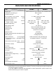
FUEL SYSTEM 8–9 Ass’y No. 000000–0000 Date : 2 Company : ISUZU No. 0–00000–0000 INJ. PUMP CALIBRATION DATA ENGINE MODEL Injection pump : PES4A 000000–0000 4BG1–T Governor : EP/RSV 000000–0000 Timing device : 1. Test Conditions : Pump rotation : clockwise (viewed from drive side) Nozzle & Nozzle Holder Ass’y : 000000–0000 (BOSCH Type No. EF8511/9A) Nozzle : 000000–0000 (BOSCH Type No. DN12SD12T) Nozzle Holder : 000000–0000 (BOSCH Type No. EF8511/9) E L MP Nozzle opening pressure : 17.
8–10 FUEL SYSTEM 3. Governor adjustment 000000–0000 Recommended speed droop adjustment screw position: 12 (notches from fully tightened position) Above 14.0 13.0 Idle-sub spring setting D Governor spring setting 9.5 A 9.1±0.1 8.5 8.0±0.1 6.5 E L P AM C 6.0 EX 6.0±0.
TURBOCHARGER 9–1 SECTION 9 TURBOCHARGER TABLE OF CONTENTS ITEM PAGE General description . . . . . . . . . . . . . . . . . . . . . . . . . . . . . . . . . . . . . . . . . . . . . . . . . . . . . . . . . . . . . . . . . . . . . . . . . . . . . . . . . . . . . . . . 9– 2 Turbocharger identification. . . . . . . . . . . . . . . . . . . . . . . . . . . . . . . . . . . . . . . . . . . . . . . . . . . . . . . . . . . . . . . . . . . . . . . . . . . . . . . 9– 3 Inspection and repair . . . . . . . . . . . . . .
9–2 TURBOCHARGER GENERAL DESCRIPTION TD04H RHG6
TURBOCHARGER 9–3 TURBOCHARGER IDENTIFICATION The IHI Turbocharger nameplate gives the date of manufacture and other important information required to identify the unit when service inquiries or part orders are made. The arrow in the illustration indicates the location of the Turbocharger nameplate. The turbocharger nameplate has the following information stamped on it. Refer to the illustration at the left. Turbo Spec. 1 (1) Turbo Specification Number, Production Year and Month Serial No.
9–4 TURBOCHARGER INSPECTION AND REPAIR If excessive wear or damage is discovered during inspection, the appropriate parts must be adjusted, repaired, or replaced. Damage or improper adjustment of the turbocharger will inhibit sufficient air flow to the engine, preventing it from delivering full performance. If the engine demonstrates a significant drop in performance, check for engine damage or wear. If no significant engine damage or wear can be found, it is likely that the turbocharger is at fault.
AIR COMPRESSOR 10–1 SECTION 10 AIR COMPRESSOR TABLE OF CONTENTS ITEM PAGE General description . . . . . . . . . . . . . . . . . . . . . . . . . . . . . . . . . . . . . . . . . . . . . . . . . . . . . . . . . . . . . . . . . . . . . . . . . . . . . . . . . . . . . . 10– 2 Disassembly steps. . . . . . . . . . . . . . . . . . . . . . . . . . . . . . . . . . . . . . . . . . . . . . . . . . . . . . . . . . . . . . . . . . . . . . . . . . . . . . . . . . . . . . . . 10– 3 Inspection and repair. . . . . . . .
10–2 AIR COMPRESSOR GENERAL DESCRIPTION AIR COMPRESSOR SECTIONAL VIEW from Governer to Air tank from Air cleaner Main Data Piston ring configuration Two compression rings and one oil ring Theoretical air delivery amount Cylinder bore × stroke Maximum operating speed 0.155 L/rev. mm (in) min-1 Crankshaft rotating ratio to engine Weight 70 (2.755) × 40 (1.574) 1650 0.5 kg 7.
AIR COMPRESSOR 10–3 DISASSEMBLY STEPS 3 2 7 1 5 4 6 8 Disassembly Steps 1. ▲ 2. 3. 4. Cylinder head and gasket Cylinder body Piston Crankcase flange 5. 6. 7. 8. Bearing cover with oil seal Bearing Connecting rod Crankshaft and bearing Important Operation 2. Cylinder body 1) Remove the cylinder mounting flange bolts. 2) Remove the cylinder with tapping out from the crankcase.
10–4 AIR COMPRESSOR INSPECTION AND REPAIR Make the necessary adjustments, repairs, and part replacements if excessive wear or damage is discovered during inspection. Cylinder Measure the uneven wear of the cylinder bore at the piston skirt position mm (in) Limit Cylinder Bore Uneven Wear 0.2 (0.0079) Measure the piston and the cylinder bore clearance. mm (in) Piston and Cylinder Bore Clearance Standard Limit 0.1–0.3 (0.0040–0.0118) 1.0 (0.
AIR COMPRESSOR 10–5 Measure the piston and the piston pin hole clearance. mm (in) Piston Pin and Piston Pin Hole Clearance Standard Limit 0.002–0.023 (0.00008–0.00091) 0.0040 (0.00016) Measure the piston pin and the connecting rod smallend clearance. mm (in) Piston Pin and Connecting Rod Small-end Clearance Standard Limit 0.002–0.026 (0.00008–0.00102) 0.1 (0.0039) Measure the air compressor crank pin and connecting rod large-end clearance. mm (in) Standard Crankpin and Connect0.02–0.
10–6 AIR COMPRESSOR REASSEMBLY STEPS 6 7 2 8 4 5 3 1 Reassembly Steps ▲ 1. Crankshaft and bearing ▲ 2. Connecting rod 3. Bearing ▲ 4. Bearing cover with oil seal 5. 6. ▲ 7. ▲ 8. Crankcase flange Piston Cylinder body Cylinder head and gasket Important Operation 1. Crankshaft and bearings 1) Install the bearings to the crankshaft. 2) Insert the crankshaft into the crankcase from the bearing cover side while tapping it gently with a soft hammer.
AIR COMPRESSOR 10–7 2. Connecting rod 1) Install the connecting rod bearing cap and tighten the cap bolts to the specified torque. N·m (kgf·m/lb.ft) Connecting Rod Cap Bolt Torque 25 (2.5/18) 4. Bearing cover 1) Remove the used O-ring from the bearing case and discard it. 2) Lubricate the inner surface of new O-ring with grease. 3) Install the O-ring to the bearing cover. 4) Install the bearing cover to the crankcase. Tighten the bearing cover bolts to the specified torque. N·m (kgf·m/lb.
MEMO
ENGINE ELECTRICALS 11–1 SECTION 11 ENGINE ELECTRICALS TABLE OF CONTENTS ITEM PAGE Starter identification . . . . . . . . . . . . . . . . . . . . . . . . . . . . . . . . . . . . . . . . . . . . . . . . . . . . . . . . . . . . . . . . . . . . . . . . . . . . . . . . . . . . . 11– 2 Starter main data and specifications . . . . . . . . . . . . . . . . . . . . . . . . . . . . . . . . . . . . . . . . . . . . . . . . . . . . . . . . . . . . . . . . . . 11– 3 Starter motor sectional view . . . . . . . . . . . .
11–2 ENGINE ELECTRICALS STARTER IDENTIFICATION The starter identification plate is attached to the starter motor outside yoke. The ISUZU part number, the manufacturer's code number, and other important information are stamped on the plate. Refer to the identification plate together with the "Main Data and Specifications" Tables and accompanying charts in this Manual when requesting service assistance from a qualified electrical repair shop.
ENGINE ELECTRICALS 11–3 STARTER MAIN DATA AND SPECIFICATIONS Isuzu Part No. Manufacturer's code No. (HITACHI) Rated voltage Rated output Rating Direction of rotation (Viewed from the pinion side) Clutch type Terminal voltage (No load) Minimum current (No load) Starter motor minimum operating speed (No load) (V) (kW) (Sec) (V) (A) (min-1) 897225-1990 1-81100-3420 S25-177 S25-172 24 4.5 30 24 4.5 30 Clockwise Roller 24 Less than 100 Clockwise Roller 24 100 More than 3500 More than 3500 3 11 40.
11–4 ENGINE ELECTRICALS STARTER MOTOR SECTIONAL VIEW Magnetic switch Gear shaft (Internal gear) Yoke Shift lever Gear case Armature Brush Pinion Brush holder Pinion gap (0.3–1.5mm/0.012–0.059in.
ENGINE ELECTRICALS 11–5 ALTERNATOR IDENTIFICATION The alternator identification plate is attached to the alternator rear bracket. The ISUZU part number, the manufacturer's code number, and other important information are stamped on the plate. Refer to the identification plate together with the "Main Data and Specifications" Tables and accompanying charts in this Manual when requesting service assistance from a qualified electrical repair shop.
11–6 ENGINE ELECTRICALS MAIN DATA AND SPECIFICATIONS ALTERNATOR Isuzu Part No. 1-81200-5301 Manufacturer's code No. (MITSUBISHI) A004T05486 Rated voltage Rated output Rated speed Rated output at r.p.m No-load output at 0 Amp. Direction of rotation as viewed from pulley side Polarity grounded Pulley diameter Coil resistance at 20°C Field coil Regulator's applicable Isuzu part No. Manufacturer's code No. (V) (A) (min-1) (Amp./Volt/min-1) (Volt/min-1) 24 50 5000 50/27/5000 24/900 Clockwise mm (in.
ENGINE ELECTRICALS 11–7 ALTERNATOR SECTIONAL VIEW STARTER ROTOR RECTIFIER BEARING PULLEY BEARING IC REGULATOR REAR BRACKET FRONT BRACKET COIL ASSEMBLY (FIELD COIL) CHARGING CURCUIT ADDITIONAL DIODES INDICATOR LAMP DIODE TRIO STARTER COIL KEY SWITCH BATTERY (24V) FIELD COIL IC REGULATOR ALTERNATOR
MEMO
TROUBLESHOOTING 12–1 SECTION 12 TROUBLESHOOTING TABLE OF CONTENTS ITEM PAGE Hard starting . . . . . . . . . . . . . . . . . . . . . . . . . . . . . . . . . . . . . . . . . . . . . . . . . . . . . . . . . . . . . . . . . . . . . . . . . . . . . . . . . . . . . . . . . . . . . . 12– 2 1) Starter inoperative . . . . . . . . . . . . . . . . . . . . . . . . . . . . . . . . . . . . . . . . . . . . . . . . . . . . . . . . . . . . . . . . . . . . . . . . . . . . . . .
12–2 TROUBLESHOOTING HARD STARTING 1) Checkpoint Neutral switch (If so equipped) Battery STARTER INOPERATIVE Trouble Cause NG NG NG NG Defective neutral switch Loose battery cable terminals Poor connections due to rusting Battery discharged or weak Fan belt loose or broken Remedy NG NG NG NG Replace the neutral switch Clean and/or retighten the battery cable terminals Recharge or replace the battery Adjust or replace the fan belt OK Fusible link NG Fusible link shorted NG Replace
TROUBLESHOOTING 12–3 HARD STARTING 2) STARTER OPERATES BUT ENGINE DOES NOT TURN OVER Checkpoint Battery Trouble Cause NG NG NG Loose battery cable terminals Poor connections due to rusting Battery discharged or weak Fan belt loose or broken Remedy NG NG NG Clean and/or retighten the battery cable terminals Recharge or replace the battery Adjust or replace the fan belt OK Starter NG NG Defective pinion gear Defective magnetic switch NG Replace the pinion gear NG Repair or replace
12–4 TROUBLESHOOTING HARD STARTING 3) ENGINE TURNS OVER BUT DOES NOT START FUEL IS BEING DELIVERED TO THE INJECTION PUMP Checkpoint Trouble Cause Remedy Continued from the previous page OK Injection nozzle NG Injection nozzle injection starting pressure too low Improper spray condition NG Adjust or replace the injection nozzle OK Injection pump NG Defective fuel injection nozzle resulting in fuel drippage after fuel injection NG Replace the delivery valve NG Defective injection pump contr
TROUBLESHOOTING 12–5 HARD STARTING 4) ENGINE TURNS OVER BUT DOES NOT START Checkpoint Engine stop mechanism Trouble Cause NG NG Defective engine stop mechanism control wire improperly adjusted (In-line pump) Defective fuel cut solenoid valve (VE pump) Remedy NG NG Replace the engine stop mechanism Adjust the control wire Replace the fuel cut solenoid valve FUEL IS NOT BEING DELIVERED TO THE INJECTION PUMP Fuel NG Fuel tank is empty NG Fill the fuel tank OK Fuel piping Repair or replac
12–6 TROUBLESHOOTING UNSTABLE LOW IDLING Checkpoint Low idling system Trouble Cause NG Low idling improperly adjusted Remedy NG Adjust the low idling OK Low idling speed control device NG Defective low idling speed control device NG Repair or replace the low idling speed control device NG Throttle control system improperly adjusted NG Adjust the throttle control system OK Throttle control system OK Fuel system NG NG NG Fuel system leakage or blockage Air in the fuel system Water
TROUBLESHOOTING 12–7 UNSTABLE LOW IDLING Checkpoint Trouble Cause Remedy Continued from the previous page OK Injection pump NG NG NG NG NG NG NG Continued on the next page Defective governor lever operation Regulator valve improperly adjusted (VE pump only) Broken plunger spring Worn plunger Worn camshaft (In-line pump only) Worn roller tappet (In-line pump only) Worn cam disc (VE pump only) NG Repair or replace the governor lever NG Adjust or replace the regulator valve NG NG NG
12–8 TROUBLESHOOTING UNSTABLE LOW IDLING Checkpoint Trouble Cause Remedy Continued from the previous page OK Valve clearance NG Valve clearance improperly adjusted NG Adjust the valve clearance OK Compression pressure NG Blown out cylinder head gasket Worn cylinder liner Piston ring sticking or broken Improper seating between the valve and the valve seat NG Replace the related parts
TROUBLESHOOTING 12–9 INSUFFICIENT POWER Checkpoint Air cleaner Trouble Cause NG Clogged air cleaner element Remedy NG Clean or replace the air cleaner element OK Fuel NG Water particles in the fuel NG Replace the fuel OK Fuel filter NG Clogged fuel filter element NG Replace the fuel filter element or the fuel filter cartridge NG Repair or replace the fuel feed pump OK Fuel feed pump NG Defective fuel feed pump OK Injection nozzle NG NG Injection nozzle sticking Injection nozz
12–10 TROUBLESHOOTING INSUFFICIENT POWER Checkpoint Trouble Cause Remedy Continued from the previous page OK Injection pump NG NG NG NG NG NG NG Continued on the next page Defective delivery valve Defective timer Improper control lever operation Defective injection timing Weak governor spring Worn plunger Worn camshaft (In-line pump only) NG NG NG NG NG NG NG Replace the delivery valve Repair or replace the timer Adjust or replace the control lever Adjust the injection timing
TROUBLESHOOTING 12–11 INSUFFICIENT POWER Checkpoint Trouble Cause Remedy Continued from the previous page OK Injection pump NG Worn roller tappet NG Replace the roller tappet OK Turbocharger NG NG Exhaust gas leakage from the exhaust system Air leakage from the intake system Defective turbocharger assembly NG NG Repair or replace the related parts Replace the turbocharger assembly OK Compression pressure NG Blown out cylinder head gasket Worn cylinder liner Piston ring sticking or bro
12–12 TROUBLESHOOTING EXCESSIVE FUEL CONSUMPTION Checkpoint Fuel system Trouble Cause NG Fuel leakage Remedy NG Repair or replace the fuel system related parts NG Clean or replace the air cleaner element OK Air cleaner NG Clogged air cleaner element OK Low idling speed NG Poorly adjusted low idle speed NG Adjust the low idle speed OK Injection nozzle NG Injection nozzle injection starting pressure too low Improper spray condition NG Adjust or replace the injection nozzle OK Fuel
TROUBLESHOOTING 12–13 EXCESSIVE FUEL CONSUMPTION Checkpoint Trouble Cause Remedy Continued from the previous page OK Turbocharger NG Defective turbocharger assembly NG Replace the turbocharger assembly OK Valve clearance NG Valve clearance improperly adjusted NG Adjust the valve clearance OK Compression pressure NG Blown out cylinder head gasket Worn cylinder liner Piston ring sticking or broken Improper seating between the valve and the valve seat NG Replace the related parts OK Valv
12–14 TROUBLESHOOTING EXCESSIVE OIL CONSUMPTION Checkpoint Engine oil Trouble Cause Remedy NG Engine oil unsuitable Too much engine oil NG Replace the engine oil Correct the engine oil volume NG Oil leakage from the oil seal and/or the gasket NG Replace the oil seal and/or the gasket OK Oil seal and gasket OK Air breather NG Clogged air breather NG Clean the air breather OK Inlet and exhaust valves Valve seals NG Defective valve seals Worn valve stems and valve guides NG Replace th
TROUBLESHOOTING 12–15 OVERHEATING Checkpoint Cooling water Trouble Cause NG Insufficient cooling water Remedy NG Replenish the cooling water OK Fan belt NG Fan belt loose or cracked causing slippage NG NG Defective radiator cap or clogged radiator core NG Replace the fan belt OK Radiator Replace the radiator cap or clean the radiator core OK Water pump NG Defective water pump NG Repair or replace the water pump OK Cylinder head and cylinder body sealing cap NG Defective sealing
12–16 TROUBLESHOOTING OVERHEATING Checkpoint Trouble Cause Remedy Continued from the previous page OK Fuel injection timing NG Fuel injection timing improperly adjusted NG Adjust the fuel injection timing
TROUBLESHOOTING 12–17 WHITE EXHAUST SMOKE Checkpoint Fuel Trouble Cause NG Water particles in the fuel Remedy NG Replace the fuel OK Fuel injection timing NG Delayed fuel injection timing NG Adjust the fuel injection timing OK Compression pressure NG Blown out cylinder head gasket Worn cylinder liner Piston ring sticking or broken Improper seating between the valve and the valve seat NG Replace the related parts OK Turbocharger NG Defective turbocharger NG Replace the turbocharger
12–18 TROUBLESHOOTING DARK EXHAUST SMOKE Checkpoint Air cleaner Trouble Cause NG Clogged air cleaner element Remedy NG Clean or replace the air cleaner element NG Adjust or replace the injection nozzle OK Injection nozzle NG Injection nozzle injection starting pressure too low Improper spray condition OK Fuel injection timing NG Fuel injection timing improperly adjusted NG Adjust the fuel injection timing OK Injection pump NG NG Defective delivery valve resulting in fuel drippage af
TROUBLESHOOTING 12–19 OIL PRESSURE DOES NOT RISE Checkpoint Engine oil Trouble Cause NG Improper viscosity engine oil Too much engine oil Remedy NG Replace the engine oil Correct the engine oil volume OK Oil pressure gauge or unit Oil pressure indicator light NG Defective oil pressure gauge or unit Defective indicator light NG Repair or replace the oil pressure gauge or unit Replace the indicator light OK Oil filter NG Clogged oil filter element NG Replace the oil filter element or the o
12–20 TROUBLESHOOTING OIL PRESSURE DOES NOT RISE Checkpoint Trouble Cause Remedy Continued from the previous page OK Camshaft NG Worn camshaft and camshaft bearing NG Replace the camshaft and the camshaft bearings NG Replace the crankshaft and/or the bearings OK Crankshaft and bearings NG Worn crankshaft and bearings
TROUBLESHOOTING 12–21 ABNORMAL ENGINE NOISE 1. Checkpoint Engine Knocking Trouble Cause Remedy Check to see that the engine has been thoroughly warmed up before beginning the troubleshooting procedure.
12–22 TROUBLESHOOTING ABNORMAL ENGINE NOISE 2. Checkpoint Gas Leakage Noise Trouble Cause Remedy Continued from the previous page OK Exhaust manifold NG Loosely connected exhaust manifold and/or glow plugs NG Tighten the exhaust manifold connections OK Cylinder head gasket NG Damaged cylinder head gasket 3.
TROUBLESHOOTING 12–23 ABNORMAL ENGINE NOISE 4.
MEMO
SPECIAL TOOL LIST 13–1 SECTION 13 SPECIAL TOOL LIST TABLE OF CONTENTS ITEM PAGE Special tool list. . . . . . . . . . . . . . . . . . . . . . . . . . . . . . . . . . . . . . . . . . . . . . . . . . . . . . . . . . . . . . . . . . . . . . . . . . . . . . . . . . . . . . . . . . . .
13–2 SPECIAL TOOL LIST SPECIAL TOOL LIST ITEM NO. ILLUSTRATION PART NO. PARTS NAME PAGE 1. 5-85317-001-0 Compression gauge adaptor 2–15 2. 1-85111-003-0 Cylinder head bolt wrench 3–8 3. 9-8521-0122-0 Crankshaft taper bushing remover 3–9 4. 5-8840-2360-0 Rear oil seal remover 3–9 5. 1-85235-0060 Valve spring compressor 3–13 5–5 6. 1-85232-001-0 9-85220-035-0 Valve guide remover and installer 4–3 7. 9-8523-1818-0 Camshaft bearing remover and installer 4–10 8.
SPECIAL TOOL LIST 13–3 ITEM NO. PART NO. PARTS NAME PAGE 11. 9-8523-1369-0 Connecting rod bushing installer 4–21 12. 9-8521-0141-0 Crankshaft gear remover 4–29 13. 9-8522-0033-0 Crankshaft gear installer 4–29 14. 9-8522-0034-0 Crankshaft front oil seal installer 4–30 15. 1-85221-005-0 Valve stem oil seal installer 5–5 16. 9-8522-1251-0 Piston ring compressor 5–12 Rear oil seal installer 5–13 17.
MEMO
REPAIR STANDARDS 14–1 SECTION 14 REPAIR STANDARDS GENERAL RULES 1. These tables provide standards relating the repair of the following diesel engine; Model AA-4BG1T, BB-4BG1T, AA-6BG1, BB-6BG1T 2. These Repair Standards are based on inspection items, together with dimensions, assembly standards, limit values, and repair procedures. (1) Nominal dimensions are the standard production values.
Name of Part Cylinder Block Engine Body Time for engine disassembly and repair Major Category L/h Lubricating oil consumption 490 (5/71.1) Pressure test: 3 minutes kPa (kgf/cm2/psi) 0.03 – 0.10 (0.001 – 0.004) 0.05 or less (0.002) A Dia. 105 (4.1339) 100% 100% Assembly Standard Value Cylinder block upper face warpage Liner projection A 20mm(0.787in) Wear on liner bore Measured at A–A L/h 3.
Name of Part Cylinder Head Major Category A Value 69 (7.0/51) ↓ 88 (9.0/65) ↓ 90° – 120° 490 (5/71.1) Water-pressure test, 3 minutes kPa (kgf/cm2/psi) Cylinder head bolts tightening torque (angular tightening method) N·m (kgf-m/lb·ft) 0.05 or less (0.002) Warpage of manifold mounting surface 1.5 (0.059) 1.0 (0.039) Assembly Standard Value 0.075 or less (0.
Main Operating Parts Name of Part Pistons Piston Ring Major Category Tension N (kgf/lb) Piston Ring Gap 0.60 – 0.75 (0.0236 – 0.0295) No. 3 compression ring Oil ring No. 3 compression ring No. 2 compression ring No. 1 compression ring 0.30 – 0.50 (0.014 – 0.020) 20.4 – 30.6 (2.08 – 3.12/ 4.59 – 6.88) 14.1 – 21.2 (1.44 – 2.16/ 3.17 – 4.76) 14.1 – 21.2 (1.44 – 2.16/ 3.17 – 4.76) 36.3 – 55.9 (3.7 – 5.7/ 8.16 – 12.6 0.60 – 0.75 (0.0236 – 0.0295) No. 2 compression ring Oil ring 0.35 – 0.50 (0.
Name of Part Piston Ring Major Category 0.15 (0.0059) 0.15 (0.0059) 0.050 – 0.090 (0.0020 – 0.0035) 0.030 – 0.070 (0.0012 – 0.0028) Oil ring 0.15 (0.0059) – Limit No. 3 compression ring – Assembly Standard Value 0.070 – 0.110 (0.0028 – 0.0043) Nominal Dimension No. 2 compression ring Ring gap orientation Clearance between piston ring and ring groove No.
Name of Part Crankshaft Major Category Ellipse and taper 0.007 (0.0003) 79.905 – 79.925 (3.1459 – 3.1467) 63.924 – 63.944 (2.5167 – 2.5175) Check dynamic balance Crankshaft balance (g-cm) 36 or less Perform lapping on gears with burrs; in cases of severe damage, replace. Replace Replace thrust bearings Undersize bearings cannot be used Replace bearing Use those with projection and proper arc; take care with back side fit Replace Replace Replace Replace Repair Procedure Ring gear 0.4 (0.
Name of Part Crankshaft Major Category Crankshaft rear oil seal wear N·m (kgf-m/lb·ft) Crankshaft bearing cap bolt torque Inspection Item Nominal Dimension 226 – 245 (23 – 25/166 – 181) Assembly Standard Value Limit In case of oil leak, replace oil seal Apply engine oil to threads and seating areas of bolts before tightening Repair Procedure Check for oil seal collapse Do not catch foreign matter in bolts Comments REPAIR STANDARDS 14–7 Main Operating Parts
Name of Part Connecting Rod Major Category Repair Procedure 192 (7.559) 20 or less Piston weight difference after assembly g 39 (4.0/29) ↓ 60° – 90° 0.05 or less (0.002) Big end to small end hole parallelism (per 100 mm) Bearing cap bolt tightening torque (angular tightening method) N·m (kgf-m/lb·ft) 0.05 or less (0.002) 0.17 – 0.30 (0.0067 – 0.
Name of Part Camshaft Major Category 0.2 (0.008) 0.050 – 0.114 (0.002 – 0.005) 7.21 (0.284) Dia. 55.6 (2.189) Dia. 55.94 – 55.97 (2.202 – 2.204) Camshaft play (front-back direction) 7.71 (0.304) 0.15 (0.006) 0.05 (0.002) Limit 0.03 – 0.09 (0.001 – 0.004) Assembly Standard Value Camshaft runout B A Dia. 56 (2.205) Dia. 56 (2.205) Nominal Dimension 0.12 (0.
Name of Part Inspection Item mm (in) mm (in) Free height Inclination Tension N (kgf/lb) (When compressed to installed length) 44.5mm(1.752in) 142 (14.5/30.9) less than 1.9 (0.075) 60.6 (2.39) 2.7 (0.106) 58.0 (2.28) 127 (13.0/28.7) Replace valve spring Don’t damage lip. Dia. 8.5 (0.335) Valve stem oil seal lip Replace oil seal Replace valve and valve guide together Apply oil to valve guide and press in Measure valve stem at three positions Comments Reference value Dia. 8.8 (0.346) 1.
Valve System Intake System Name of Part Valves Air cleaner Major Category Air cleaner element condition Dia. 18.85 (0.742) 18.98 – 19.00 (0.747 – 0.748) Rocker arm shaft wear Limit 0.2 (0.0079) 0.4 (0.016) Assembly Standard Value 0.01 – 0.05 (0.0004 – 0.
Lubricating System 0.032 – 0.070 (0.0013 – 0.0028) 0.045 – 0.078 (0.0018 – 0.0031) Clearance between drive shaft and pump body Clearance between drive shaft and bushing Initial operating pressure of main oil filter relief valve kPa (kgf/cm2/psi) Clogging and damage to oil filter Initial operating Oil gallery pressure of relief valve kPa (kgf/cm2/psi) Oil pump Diameter of drive shaft 196 (2.0/28) 785 (8/114) 441 (4.5/64) 0.040 – 0.094 (0.0016 – 0.0037) End gap between pump cover and gear Dia.
Name of Part Water pump Major Category ) 6BG1 mm (in) 4BG1 Replace water pump ASM 0.14 or less (0.006) Pulley and fan center clearance Replace water pump ASM Replace water pump ASM Temperature at which thermostat lift reaches 10mm(0.394in) or more. Adjust Repair or replace if impeller and pump body are touching Replae Repair Procedure 0.020 – 0.060 (0.0008 – 0.0024) 0.2 (0.0079) Limit Bearing shaft and impeller interference 95°C (203°F) 82 ± 2°C (179.6 ± 35.6°F) About 8 – 12 (0.315 – 0.
Injection pump Fuel System Piping, etc. Name of Part Limit Repair Procedure Delivery valve wear Inspect for damage to valve’s piston and seat; replace in case of severe vertical cracks on piston or impact scars on seat with loss of finish gloss. Immerse delivery valve in clean diesel fuel, then lightly press lower part of valve seat with finger and release; replace assembly if valve does not return to original state when finger is released.
Name of Part Inspection Item Assembly Standard Value 1-15603-328-0 Repair Procedure 1075 450 10.3 (0.4449) Approx 7.5 (0.295) – A C D 100 Pump speed (min-1) Rack position mm (in) Adjustment point Fuel temperature 150 ± 5 9 ± 1.3 89 ± 1.5 Injection q’ty (mm3/1000 strokes) °C (°F) mm (in) Pipe (o.d. x i.d. x lenght) Test fuel 157 (1.6/23) kPa (kgf/cm2/psi) Fuel pumping pressure – ± 14 ±2 Max. var bet.
Name of Part Injectipn pump Major Category 7.3±0.3 7.5 8.0 9.8±0.1 10.3 10.9±0.1 11.0 Above 14.
(MITSUBISHI 1-81200-530-1) Alternator 24V, 50A Fuel system Electrical Charge/ Wiring Discharge indication Injection Nozzle Name of Part Repair Procedure Rated output current 27 V (5000 min-1) Bearing chatter Shaft runout 50A 0.06 or less (0.0024) 0.1 (0.0038) Replace bearings Replace rotor Repair Replace faulty parts Check for looseness, cuts or damaged insulation to wiring. 1 Visually inspect, no relatively large drops scattered. 2 No drops scattered to one side.
Electrical Name of Part Starter 24V, 7.4 kW (HITACHI 1-81100-342-0) Preheater Battery Major Category Unloaded characteristics (24V, 100A or less) Pinion shaft (shaft) Front (armature) Rear side (armature) Undercut depth O.D. Electrolyte turbidity Plates, separator plates, container, etc. Battery terminals Dia. 16 (0.630) Dia. 16 (0.630) Dia. 28 (1.102) 3500 min-1 0.5 – 0.8 (0.02 – 0.031) 1.31 20°C (68°F) Shant coil resistance value (Ω) 22 (0.866) Assembly Standard Value 0.
Final Inspection Electrical Name of Part Battery Major Category 110% or less Fuel consumption check 30 minutes or more Repair Procedure 290 (3.0/43) Adjust Inspect 2.5 (26/370) Inspect Limit 290 – 590 200 or less (3.0 – 6.0/43 – 85) (2.0/28) 3.0 (31/441) Assembly Standard Value 85% or more Nominal Dimension Output check Lubricating oil pressure kPa (kgf/cm2/psi) Difference in compression between cylinders kPa (kgf/cm2/psi) [water temp.
MEMO
CONVERSION TABLE 15–1 SECTION 15 CONVERSION TABLE TABLE OF CONTENTS ITEM PAGE LENGTH . . . . . . . . . . . . . . . . . . . . . . . . . . . . . . . . . . . . . . . . . . . . . . . . . . . . . . . . . . . . . . . . . . . . . . . . . . . . . . . . . . . . . . . . . . . . . . . . . . . 15– 2 AREA . . . . . . . . . . . . . . . . . . . . . . . . . . . . . . . . . . . . . . . . . . . . . . . . . . . . . . . . . . . . . . . . . . . . . . . . . . . . . . . . . . . . . . . . . . . . . . . . . . . . . . .
15–2 CONVERSION TABLE LENGTH FEET TO METERS ft. ––– 10 20 30 40 50 60 70 80 90 100 0 1 2 3 4 5 6 7 8 9 m m m m m m m m m m –––0 3.048 6.096 9.144 12.192 15.240 18.288 21.336 24.384 27.432 30.480 0.305 3.353 6.401 9.449 12.497 15.545 18.593 21.641 24.689 27.737 30.785 0.610 3.658 6.706 9.754 12.802 15.850 18.898 21.946 24.994 28.042 31.090 0.914 3.962 7.010 10.058 13.106 16.154 19.202 22.250 25.298 28.346 31.394 1.219 4.267 7.315 10.363 13.411 16.459 19.507 22.555 25.603 28.651 31.
CONVERSION TABLE 15–3 AREA SQUARE INCHES TO SQUARE CENTIMETERS in2 ––– 10 20 30 40 50 60 70 80 90 100 in2 0 1 2 3 4 5 6 7 8 9 cm2 cm2 cm2 cm2 cm2 cm2 cm2 cm2 cm2 cm2 –––00 64.516 129.032 193.548 258.064 322.580 387.096 451.612 516.128 580.644 645.160 6.452 70.968 135.484 200.000 264.516 329.032 393.548 458.064 522.580 587.096 651.612 12.903 77.419 141.935 206.451 270.967 335.483 399.999 464.515 529.031 593.547 658.063 19.355 83.871 148.387 212.903 277.419 341.935 406.451 470.
15–4 CONVERSION TABLE VOLUME GALLONS (U.S.) TO LITERS U.S. gal. ––– 10 20 30 40 50 60 70 80 90 100 0 1 2 3 4 5 6 7 8 9 liters liters liters liters liters liters liters liters liters liters U.S.gal. –––00 37.8543 75.7085 113.5628 151.4171 189.2714 227.1256 264.9799 302.8342 340.6884 378.5427 3.7854 41.6397 79.4940 117.3482 155.2025 193.0568 230.9110 268.7653 306.6196 344.4739 382.3281 7.5709 45.4251 83.2794 121.1337 158.9879 196.8422 234.6965 272.5507 310.4050 348.2593 386.1136 11.
CONVERSION TABLE 15–5 MASS POUNDS TO KILOGRAMS lbs. ––– 10 20 30 40 50 60 70 80 90 100 0 1 2 3 4 5 6 7 8 9 kg kg kg kg kg kg kg kg kg kg lbs. –––0 4.536 9.072 13.608 18.144 22.680 27.215 31.751 36.287 40.823 45.359 0.454 4.989 9.525 14.061 18.597 23.133 27.669 32.205 36.741 41.277 45.813 0.907 5.443 9.979 14.515 19.051 23.587 28.123 32.658 37.194 41.730 46.266 1.361 5.897 10.433 14.968 19.504 24.040 28.576 33.112 37.648 42.184 46.720 1.814 6.350 10.886 15.422 19.958 24.494 29.
15–6 CONVERSION TABLE PRESSURE POUNDS PER SQUARE INCHES TO KILOGRAMS PER SQUARE CENTIMETERS lb/in2 0 1 2 3 4 5 6 7 8 9 lb/in2 (psi) kg/cm2 kg/cm2 kg/cm2 kg/cm2 kg/cm2 kg/cm2 kg/cm2 kg/cm2 kg/cm2 kg/cm2 (psi) ––– 10 20 30 40 50 60 70 80 90 100 –––0 0.7031 1.4061 2.1092 2.8123 3.5154 4.2184 4.9215 5.6246 6.3276 7.0307 0.0703 0.7734 1.4764 2.1795 2.8826 3.5857 4.2887 4.9918 5.6949 6.3979 7.1010 0.1406 0.8437 1.5468 2.2498 2.9529 3.6560 4.3590 5.0621 5.7652 6.4682 7.1713 0.2109 0.
CONVERSION TABLE 15–7 TORQUE FOOT POUNDS TO KILOGRAMMETERS ft. lbs. ––– 10 20 30 40 50 60 70 80 90 100 0 1 2 3 4 5 6 7 8 9 kg-m kg-m kg-m kg-m kg-m kg-m kg-m kg-m kg-m kg-m ft lbs. –––0 1.383 2.765 4.148 5.530 6.913 8.296 9.678 11.061 12.443 13.826 0.138 1.521 2.903 4.286 5.669 7.051 8.434 9.816 11.199 12.582 13.964 0.277 1.659 3.042 4.424 5.807 7.190 8.572 9.955 11.337 12.720 14.103 0.415 1.797 3.180 4.563 5.945 7.328 8.710 10.093 11.476 12.858 14.241 0.553 1.936 3.318 4.701 6.
15–8 CONVERSION TABLE TEMPERATURE FAHRENHEIT TO CENTIGRADE °F °C °F °C °F °C °F °C °F °C °F °C °F °C °F °C -60 -58 -56 -54 -52 -50 -48 -46 -44 -42 -40 -38 -36 -34 -32 -30 -28 -26 -24 -22 -20 -18 -16 -14 -12 -10 -8 -6 -4 -51.1 -50.0 -48.9 -47.8 -46.7 -45.6 -44.4 -43.3 -42.2 -41.1 -40.0 -38.9 -37.8 -36.7 -35.6 -34.4 -33.3 -32.2 -31.1 -30.0 -28.9 -27.8 -26.7 -25.6 -24.4 -23.3 -22.2 -21.1 -20.0 -2 0 2 4 6 8 10 12 14 16 18 20 22 24 26 28 30 32 34 36 38 40 42 44 46 48 50 52 54 -18.9 -17.8 -16.
Copyright reserved for this manual may not be reproduced or copied, in whole or in part, without the written consent of ISUZU MOTORS LIMITED. WORKSHOP MANUAL (INDUSTRIAL) AA-4BG1T, AA-6BG1 BB-4BG1T, BB-6BGIT (IDE-2370) Issued by ISUZU MOTORS LIMITED POWERTRAIN SERVICE & PARTS POWERTRAIN OPERATIONS 6-26-1, Minami-oi, Shinagawa-ku,Tokyo, 140-8722, Japan TEL 03-5471-1111 First edition Dec.
IDE-2370 PRINTED IN JAPAN