
Workshop Manual

ENGINE ASSEMBLY III 5–15
Important Operations
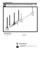
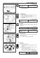
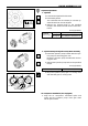
1. Flywheel
1) Lubricate the flywheel bolt threads.
2) Install the flywheel.
The crankshaft rear end dowel pin and the fly-
wheel dowel hole must be aligned.
3) Tighten the flywheel bolts to the specified
torque in the numerical order shown in the illus-
tration.
N·m (kgf·m/lb.ft)
Lubricate with
engine oil
1
6
5
2
4
3
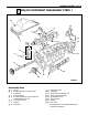
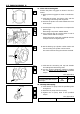
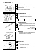
2. Injection Pump and Injection Pump Gear Assembly
1) Install the injection pump bracket with the injec-
tion pump to the timing gear case.
Dowel the injection pump bracket with the tim-
ing gear case.
2) Tighten the injection pump bolts to the specified
torque.
N·m (kgf·m/lb.ft)
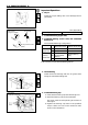
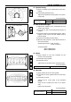
3) Align the injection pump gear "C" timing mark
with the idler gear "C" timing mark.
Injection pump gear
Idle gear
“B” mark
Camshaft
gear
Crankshaft gear
“A” mark
“C” mark
Air Compressor Installation (If so equipped)
1. Align the air compressor crankshaft spline end
marks and the injection pump drive gear shaft
female spline marks.
Flywheel
4B engine 142–172(14.5–17.5/105–127)
Bolt Torque
6B engine 197–240(20.1–24.5/145–177)
Injection Pump Bolt Torque 21 – 30 (2.1 – 3.1/15 – 22)