
Workshop Manual

1–18 GENERAL INFORMATION
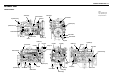
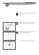
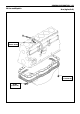
5. Draw another line (C-D) on the face of each of the
parts to be clamped. This line should be an exten-
sion of the line [A-B].
6. Draw another line [F-G] on the face of each of the
parts to be clamped. This line will be in the direc-
tion of the specified angle (Q) across the center [E]
of the nut or bolt.
Coinciding line
Specified angle (Q)
E
F
G
Line
A
BC
D
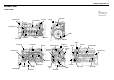
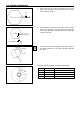
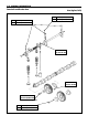
7. Use a socket wrench to tighten each nut or bolt to
the point where the line [A-B] is aligned with the
line [F-G].
Tighten
A
B
C
D
F
G
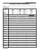
Example: Specified Angle and Tightening Rotation
A30° 1/12 of a turn
B60° 1/6 of a turn
C90° 1/4 of a turn
D 180° 1/2 of a turn
E 360° One full turn
A
B
C
D
E