
Workshop Manual

2–8 MAINTENANCE
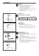
Adjust the No. 1 or the No. 6 (No. 4 for the 4BG1)
cylinder valve clearances while their respective
cylinders are at TDC on the compression stroke.
mm (in)
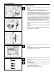
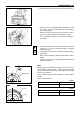
3. Loosen each valve clearance adjusting screw as
shown in the illustration.
4. Insert a 0.40 mm (0.016 in) feeler gauge between the
rocker arm and the valve stem end.
5. Turn the valve clearance adjusting screw until a
slight drag can be felt on the feeler gauge.
6. Tighten the lock nut securely.
Intake and Exhaust
Valve Clearance (cold)
0.40 (0.016)
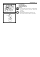
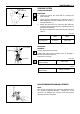
1. Bring the piston in either the No. 1 cylinder or the
No. 6 cylinder to Top Dead Center on the compres-
sion stroke by turning the crankshaft until the TDC
notched line on the crankshaft pulley is aligned with
the timing pointer.
2. Check to see if there is play in the No. 1 intake and
exhaust valve rocker arms.
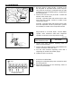
If the No. 1 cylinder intake and exhaust valve rocker
arms have play, the No. 1 piston is at TDC on the
compression stroke.
If the No. 1 cylinder intake and exhaust valve rocker
arms are depressed, the No. 6 piston (No. 4 piston
for the 4BG1) is at TDC on the compression stroke.
6
12
20
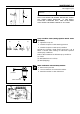
7. Rotate the crankshaft 360°.
Realign the crankshaft pulley TDC notched line with
the timing pointer.
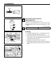
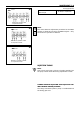
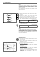
8. Adjust the clearances for the remaining valves as
shown in the illustration.
When No.1 cylinder at TDC
in compression stroke
Front
6B