
Workshop Manual

MAINTENANCE 2–11
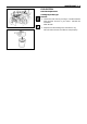
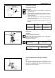
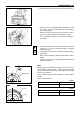
6. Hold the fuel control lever at the fully open position.
7. Slowly turn the crankshaft pulley clockwise, at the
same time, continue to feed the fuel with pumping
the priming pump.
When the fuel stop to flow out from the No. 1 deliv-
ery valve holder, stop the pump instantaneously.
This crankangle position is the injection starting of
the engine.
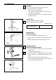
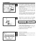
8. Observe and make sure that mark (injection starting
angle line a°) on the crankshaft pulley is aligning
with the pointer.
The timing line shows the injection starting angle of
the engine.
Blow out the remaining fuel from the delivery valve
holder.
Make sure that there is no fuel being delivered from
the priming pump.
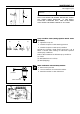
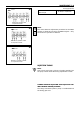
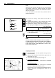
Note
6BG1 engine has eight timing notch lines punched on
the crankshaft damper pulley. 4BG1 engine has eight
timing notch lines punched on gear case side, and TDC
mark on crank pulley.
These notched lines must be aligned for correct engine
timing.
Refer to the illustration.
Degree
Degree
20
6
12
TDC
6BG1
Damper pulley
4BG1
20
16
12
8
T
Gear case
Pulley
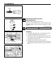
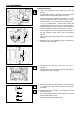
6BG1
Injection Timing B.T.D.C 8
4BG1
Injection Timing B.T.D.C 9
6BG1
4BG1
015ES002