
Workshop Manual
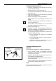


ENGINE ASSEMBLY II 4–27
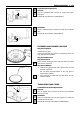
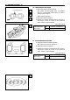
Crankshaft Pin Bearing Clearance
1. Clean the crankshaft, the connecting rod, the bear-
ing cap, and the bearings.
2. Install the bearing to the connecting rod.
Do not allow the crankshaft to move when installing
the bearing cap.
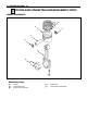
3. Hold the connecting rod (with the bearing installed)
against the crankshaft pin.
4. Attach the plastigage to the crankshaft pin.
Apply engine oil to the plastigage to keep it from
falling.
5. Install the connecting rod bearing cap and tighten it
to the specified torque.
Do not allow the connecting rod to move when
installing and tightening the bearing cap.
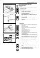
6. Remove the bearing cap.
7. Compare the width of the plastigage attached to
either the crankshaft or the bearing against the scale
printed on the plastigage container.
If the measured value exceeds the limit, perform the
following additional steps.
1) Use a micrometer to measure the crankshaft
outside diameter.
2) Use an inside dial indicator to measure the bear-
ing inside diameter.
3) Replace the crankshaft and/or the bearing if the
measured value(s) exceed the limit.
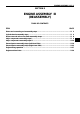
Crankshaft Tufftriding Inspection
Inspection
Model AA-4BG1T, BB-4BG1T, AA-6BG1 and BB-6BG1T
1. Use an organic cleaner to thoroughly clean the
crankshaft. There must be no traces of oil on the
surfaces to be inspected.
2. Prepare a 10% solution of ammonium cuprous chlo-
ride (dissolved in distilled water).
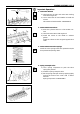
3. Use a spot glass rod to apply the solution to the sur-
face to be inspected.
Hold the surface to be inspected perfectly horizontal
to prevent the solution from running.
Note:
Do not allow the solution to come in contact with the oil
ports and their surrounding area.
Test liquid should
not be applied to
area around oil
port
Ammonium cuprous
chloride
Face in contact
with crank pin
or journal
Appox. 10m
m