2.
TABLE OF CONTENTS 1. Description of the units ....................................... ........................3 1. Quick Set Up and Operation .......................................................4 2. Installation....................................................................................5 3. Guidelines For Best Performance................................................6 4. Troubleshooting Guide.................................................................7 5. Technical Specifications..........
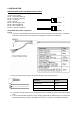
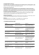
DESCRIPTION Receiver Antenna Connection Audio Jack Input Terminal For charging Modular Jack Green LED: In-use, Record RED LED: Charging Green LED: Full charge Transmitter Green: In-use (Light On) Record (Flashing) RED LED: Out of Range RED LED: Low Battery Record Button Emergency Button Lapel Mic.
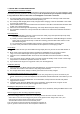
1. QUICK SET UP AND OPERATION Synching Up the Transmitter and Base The synch operation only needs to be performed the first time a system is used, or a new bodypack is used with a base previously synched to another bodypack. Do not perform the synch operation multiple times; it only needs to be done one time when a new bodypack is used with a new base. 1) 2) 3) 4) 5) Turn the transmitter power switch to ON and place the transmitter in the recharge cradle of the base.
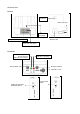
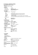
2. INSTALLATION PIN DESCRIPTION OF THE BASE OUTPUT PORT Connector wire (RJ45) Pin #1 : Transmitter Audio out Pin #2 : In Car Mic. Audio out Pin #3 : 12V DC_IN Pin #4 : Ground Pin #5 : Record Trigger OUT Pin #6 : Record Trigger IN Pin #7 : Panic Trigger Out Pin #8 : In Car Mic. Trigger IN 8 1 1 8 Type A 1) Wire the un-terminated signal wires to the control unit according to the signal chart. 5 Amp fast blow fuse is recommend in the 12VDC power supply line to protect the equipment.
Type B Wire the un-terminated signal wires to the control unit according to the signal chart. A 5 Amp fast blow fuse is recommend in the 12VDC power supply line to protect the equipment. Pin #1 : Transmitter Audio out Pin #2 : In Car Mic. Audio out Pin #3 : 12V DC_IN Pin #4 : Ground Pin #5 : Record Trigger Out Pin #6 : Record Trigger IN Pin #7 : Panic Trigger Out Pin #8 : In Car Mic. Trigger IN 1 8 Type C Wire the un-terminated signal wires to the control unit according to the signal chart.
Using Multiple Wireless Systems The PW24 system has 95 possible “channels” that are really different frequency hopping schemes. Each synchronized base and transmitter will automatically find a clear channel so up to 40 systems can work together in one location depending on other interference problems Potential Sources of Interference There are many potential sources of interference for your wireless system.
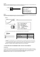
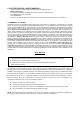
5. TECHNICAL SPECIFICATIONS RECEIVER BASE STATION Controls Video Trigger Active +12/GND Indicators INUSE LED: CHARGE LED : GREEN CHARGING -> RED FULL CHARGED -> GREEN RECORD LED Connections GREEN FLASHING In Car Mic. Un-terminated Cord RED BLUE YELLOW ORANGE BLACK GRAY Audio Connector Tip Ring Sleeve 2.
6. FACTORY SERVICE ( NORTH AMERICA ) If factory service is required, ship the unit prepaid in its original carton to: Wonwoousa Service c/o Wonwoousa 2580 E. Philadelphia St. Suite A, Ontario, CA 91761 U.S.A. Tel:909/930-2320 or 888-4-966-966 Fax: 909/930-2321 Enclose a note describing the problem along with any other pertinent information and how to contact you 7.
FCC RF RADIATION EXPOSURE STATEMENT Your transmitter contains a low power transmitter. When the Push-to Talk button is pushed it sends out radio frequency (RF) signals. This device is authorized to operate at a duty factor not to exceed 50% in MARCH 2008 the Federal Communications Commission (FCC) adopted RF exposure guidelines with safety levels for handheld wireless devices. CAUTION: To maintain compliance with the FCC’s RF exposure guidelines, hold the transmitter and antenna at least 1.0 inches (2.
Li-ion Battery safety precautions l Use only the following type and the size battery : 1300mAh, 3.6V (Li-ion /3.6V, or equivalent) l Do not dispose of the battery in a fire. The cell may explode. Check with local codes for possible special disposal instructions. l Do not connect the positive terminal and the negative terminal of the battery to each other with any metal object (such as wire). l Do not carry or store the batteries together with necklaces, hairpins, or other metal objects.