
User's Manual


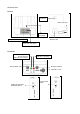

Type B
Wire the un
-
terminated signal wires to the control unit according to the signal chart. A 5 Amp fast blow fuse is
recommend in the 12VDC power supply line to protect th
e equipment.
Type C
Wire the un
-
terminated signal wires to the control unit according to the signal chart. A 5 Amp fast blow fuse is
recommend in the 12VDC power supply line to protect the equipment.
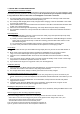
1)
Plug the 3.5mm
stereo plug into the audio input jack of the recording device.
2)
If it is to be used, plug in the in
-
car microphone into the In
-
Car Mic jack in the s
ide of the receiver
base.
3)
Turn on the transmitter and place it in the charging cradle with the beltclip facing out. The Charge
LED will light if there is power. If the LEDs do not come on, check the connections and repeat.
Installation is complete. Refer t
o Operation Section for more information.
3.
GUIDELINES AND RECOMMENDATIONS FOR BEST PERFORMANCE
Compatibility
The transmitter and receiver must synchronize to work together (see Synch process on page 3). The synch
operation only needs to be performed
the first time a system is used, or when a new bodypack is used with a
base previously synched to another bodypack.
Do not synch multiple times, just once until a new
bodypack is used.
Any Base can be synchronized with any Transmitter.
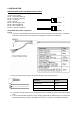
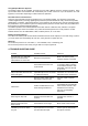
Description
Position
Audio Ground
Sleeve
Transmitter Audio
Ring
Inside Car Mic. Audio
Tip
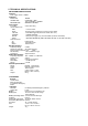
Pin
#1 : Transmitter Audio out
Pin #2 : In Car Mic. Audio out
Pin #3 : 12V DC_IN
Pin #4 : Ground
Pin #
5 : Record Trigger Out
Pin #6 : Record Trigger IN
Pin #7 : Panic Trigger Out
Pin #8 : In Car Mic. Trigger IN
8
1