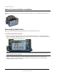
CHAPTER 5 National (Lancaster) Meter Installation This chapter provides instructions to install the 100G ERT module on 175 - 250 CFH National (Lancaster) meters. Removing the Meter Index Begin the module installation by removing the index cover and index from the meter. To remove the index from the meter 1. Remove any tamper seals from the index cover screws. Remove the index cover screws and the index cover from the meter. Discard the index cover mounting screws and index cover.
National (Lancaster) Meter Installation 4. Remove the screw completely after the index is free of the meter. 5. Set the index aside where it will not be damaged or fill with dirt, rain, or snow. You will mount the index in the ERT module later in this procedure. 6. Discard the index mounting screws. The 100G for National (Lancaster) meters includes new, differentsized index mounting screws (see Installation Prerequisites on page 14 for screw information). 7.
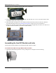
National (Lancaster) Meter Installation 2. Set the ERT cover aside where it will not be damaged or fill with rain, dirt, or snow. You will use the cover later in this installation procedure. Caution Use only dial-type indexes from National, Actaris, Schlumberger, or Sprague meters with the 100G. Indexes with bow-tie shaped wrigglers are not compatible with the 100G. You must use a compatible index.
National (Lancaster) Meter Installation 4. Attach the screw to the ERT housing's right-index mounting post just enough to hold the screw and the right end of the index in place. 5. For indexes with legs (mounting slots), screw one 10 - 20 x 3/8-inch screw (SCR-0017-001, see Installation Prerequisites on page 14 for screw information) into the right index mounting post one or two turns. Do not completely tighten the screw. 6. Place the right index mounting screw slot under the screw head.
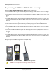
National (Lancaster) Meter Installation Programming the 100G Gas ERT Module Assembly Program the 100G, 100G DL, 100G DLN, or 100G DLT ERT modules using: • • • An FC200SR handheld computer with Field Deployment Manager (FDM) software version 1.1 or higher or A FC300 with SRead handheld computer with Field Deployment Manager (FDM) software version 1.1 or higher or A 900MHz Belt Clip Radio with Field Deployment Manager (FDM) software version 1.1 or higher and a customer-supplied laptop.
National (Lancaster) Meter Installation Take note of the index drive rate shown on a top right dial on the index. The endpoint is programmed based on the drive rate. National/Lancaster meter index drive rates are typically 2-cubic feet. To program the ERT module assembly 1. Program the meter drive rate into the 100G series gas ERT module using the endpoint programming device. 2. For all programming and Check Endpoint operations, hold the handheld programmer as close to vertical as possible.
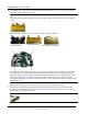
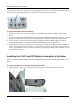
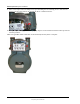
National (Lancaster) Meter Installation 2. Carefully place the 100G on the meter. Warning Failure to correctly align the meter drive post and ERT module wriggler can cause binding and lead to poor registration or meter failure. If there is a gap between the ERT module gasket and the meter, it may be the wriggler of the ERT module is dead-headed against the meter drive dog as shown in the following illustration. Remove the 100G assembly and repeat the alignment procedure.
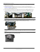
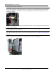
National (Lancaster) Meter Installation 5. Rotate the ERT module down until the ERT module mounting hole is approximately 1/4-inch below the meter index mounting hole. 6. Rotate the ERT up to align the left mounting holes. Raising and lowering the ERT module on the meter drive post facilitates the proper positioning and engagement of ERT module wriggler with the meter drive post. 7. Insert the left mounting screw and tighten a few turns. 8.
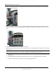
National (Lancaster) Meter Installation 9. Place a new tamper seal in the tamper seal cups surrounding the two mounting screws. Press the new tamper seals into place using an 11/32-inch nut driver or similar blunt tool. 10. Complete any necessary paperwork and properly dispose excess installation materials and scrap from the customer premises. 100G series gas ERT module installation on the National (Lancaster) meter is complete.
CHAPTER 6 Elster American and Itron Commercial Meter Installation This chapter provides instructions to install the 100G on Elster American meter and Itron commercial meters. Warning Handle the commercial 100G carefully so the metal passive radiator antenna is not damaged. Removing the Index or Index Assembly from the Meter Commercial ERT modules mount on Elster American meters in various configurations.
Elster American and Itron Commercial Meter Installation Index covers may (or may not) have tamper seal cups (on the back of the cover) for added security. Index removal assumes the installer removes any tamper seals or wires before continuing with these instructions. Note It may not be necessary to dismantle your commercial index assembly (index and cover). These instructions do not include index/cover assembly for those applications.
Elster American and Itron Commercial Meter Installation 4. Remove the mounting plate screws and separate the mounting plate from the meter. Place the mounting plate where it will not be damaged. You may use it later in this installation. Programming the 100G Datalogging Commercial Gas ERT Program commercial 100G, 100G DL, 100G DLN, or 100G DLT ERT modules using: • • • An FC200SR handheld computer with Field Deployment Manager (FDM) software version 1.
Elster American and Itron Commercial Meter Installation To enable enhanced security and for more complete programming information, see the Field Deployment Manager Endpoint Tools Mobile Application Guide (TDC-0934). FC200SR FC300 with SRead 900MHz Belt Clip Radio Caution You must program the 100G commercial ERT module before use. Take note of the index drive rate shown on the index. The ERT is programmed based on the drive rate.
Elster American and Itron Commercial Meter Installation 4. Slowly turn the ERT module's drive shaft two turns in the direction shown on the index drive rate. This verifies the ERT module is counting properly. Caution Do not turn the drive shaft faster than one turn per second. 5. Read or Check the 100G using the endpoint programming device. • If the read result is higher than the number programmed in Step 1, the 100G is counting correctly.
Elster American and Itron Commercial Meter Installation 2. Align the ERT module so the screw holes line up with the meter's top screw holes. Carefully lower the module on the meter with the wriggler notches lining up with the meter's drive dog teeth. Warning The INLET label on the 100G must line up with the INLET label on the meter case. 3. Verify the bottom of the ERT module and the top of the meter meet. The ERT module housing should rest on top of the meter without gaps.
Elster American and Itron Commercial Meter Installation 5. Install four mounting screws included with the ERT module and tighten them in an alternating diagonal sequence. For metal mounting plates with a flat screw surface, use ERT module mounting screws with internal tooth washers. For plastic mounting plates with tamper screw cups, use ERT module mounting screws (use O-ring AS-568A-011, 5/16" ID x 7/16-inch OD for a maximum moisture seal).
Elster American and Itron Commercial Meter Installation This completes installation of the commercial gas ERT module on an Elster American Meter commercial meter. Attaching the Commercial 100G Gas ERT Module to an Itron Commercial Meter This section provides instructions for installing the 100G on the Itron, Sprague, Actaris, or Schlumberger 675A, 800A, and 1000A commercial meter. Installation requires an Itron adapter kit available from Itron, Owenton, KY.
Elster American and Itron Commercial Meter Installation Itron Adapter Kit Materials (Part Number 80005901-001) Itron Part Number (Kit Component) Tamper seals 017167 Extension driver 550417 Optional Installation Materials (available from Itron) Index cover Itron Part Number Commercial index Various Index mounting screws dial index odometer index 010040 090071 80006001 To remove the index cover 1.
Elster American and Itron Commercial Meter Installation To remove the index and index mounting bracket 1. Remove the two screws holding the index bracket to the meter. 2. To remove a dial index, loosen the two screws holding the index to the index bracket in an alternating pattern: • Loosen the right index mounting screw two turns. • Loosen the left index mounting screw two turns.
Elster American and Itron Commercial Meter Installation 2. Insert the dial index mounting screws (part number 010040) in the index mounting bracket. Tighten the index mounting screws just enough to secure them in the index mounting bracket. 3. Slide the index mounting legs (1) all the way to the right over the index screws. The mounting bracket drive dog must engage with the index wriggler (2).
Elster American and Itron Commercial Meter Installation 2. Align the mounting bracket drive dog with the index wriggler. Warning Failure to properly engage the mounting bracket drive dog and index wriggler may cause binding and meter failure. 3. Insert the odometer index mounting screws through the index mounting hole and into the mounting bracket. 4. Tighten the index mounting screws in an alternating pattern. Tighten (torque) the index mounting screws to 3 - 6 inch-pounds.
Elster American and Itron Commercial Meter Installation The 100G DLS ERT modules support enhanced security with the Itron Security Manager. Enabling command or enhanced security requires additional programming. Program the 100G DLS ERT modules using: • • • An FC200SR handheld computer with Field Deployment Manager (FDM) software version 3.3 or higher or An FC300 with SRead handheld computer with Field Deployment Manager (FDM) software version 3.
Elster American and Itron Commercial Meter Installation To program the commercial ERT module 1. Program the index drive rate into the 100G series gas ERT module using the endpoint programming device. 2. For all programming and Check Endpoint operations, hold the handheld as close to vertical as possible. For best success, keep the handheld programmer within 6 feet of the target ERT module. 3.
Elster American and Itron Commercial Meter Installation Warning Failure to properly align the 100G DLS wriggler with the meter drive post can cause binding and lead to poor registration or meter failure. 4. Inlet lettering on the commercial gas ERT module must line up with Inlet lettering on the meter. 5. Slowly lower the module onto the Itron commercial meter. Carefully align the meter drive dog and commercial ERT module wriggler. The ERT housing should rest on the top of the meter without gaps.
Elster American and Itron Commercial Meter Installation To install the index and cover assembly on the commercial module 1. Place the extension driver on the commercial module wriggler. Apply a little pressure to ensure the extension driver seats securely on the commercial module wriggler. 2. Place the Itron adapter plate on the commercial gas module with the two small screw holes in the adapter plate to the back of the meter.
Elster American and Itron Commercial Meter Installation 5. Secure with the four mounting screws from the adapter kit. Tighten the mounting screws in a diagonal alternating pattern. • Insert the first screw and tighten enough to hold the index in place. • Insert the second screw and tighten two to three turns. • Insert the third mounting screw and tighten two to three turns. • Insert the fourth mounting screw and tighten. 6. Tighten the first, third and second screw using an alternating tightening pattern.
CHAPTER 7 Sensus Commercial Meter Installation This chapter provides instructions to install the commercial gas ERT module on a Sensus commercial diaphragm meter. Note Sensus meters are also known as Invensys or Rockwell meters. For these instructions, all meter types are referred to as Sensus meters. Warning Handle the commercial gas ERT module carefully so the metal passive radiator antenna is not damaged.
Sensus Commercial Meter Installation To remove the index from the meter 1. Remove any tamper seals (or wire seals) from the index cover and remove the index cover mounting screws. You will reinstall it later in these instructions. 2. Remove the index screws from the meter. Set the index cover aside where it will not be damaged or fill with dirt, rain or snow. You will re-install the index later in this procedure.
Sensus Commercial Meter Installation The 100G DLS ERT modules support enhanced security with the Itron Security Manager. Enabling command or enhanced security requires additional programming. Program the 100G DLS ERT modules using: • • • An FC200SR handheld computer with Field Deployment Manager (FDM) software version 3.3 or higher or An FC300 with SRead handheld computer with Field Deployment Manager (FDM) software version 3.
Sensus Commercial Meter Installation To program the commercial ERT module Program the index drive rate into the commercial ERT module using the endpoint programming device. For all programming and Check Endpoint operations, hold the handheld programmer as close to vertical as possible. For best success, keep the handheld programmer within 6 feet of the target ERT module.
Sensus Commercial Meter Installation 2. Align the ERT module so the screw holes line up with the meter's top screw holes. Carefully lower the ERT on the meter so the wriggler's bars line up with the meter drive dog. Itron recommends installation with one bar inserted into the meter drive dog's u-shaped gear. Warning The INLET label on the commercial gas ERT module must line up with the INLET label on the Sensus meter case. 3. Verify the bottom of the ERT module and the top of the meter meet.
Sensus Commercial Meter Installation • For index covers with tamper seal cups, use screws, (AS-568A-011, 5/16" ID x 7/16 OD) O-rings, and tamper seals. 7. Place new tamper seals over screws (if mounting plate has tamper seal cups) and press into place with an 11/32-inch nut driver or similar blunt tool. 8. If your mounting assembly requires a utility-approved wire seal, pass wires through holes in the screw heads and crimp the approved wire seal.
Sensus Commercial Meter Installation Mounting a 100G Gas ERT Module on a Rockwell 750 meter with an Aluminum BOX Direct Reading (VDR) Installing the 100G series commercial gas ERT module on a Rockwell commercial meter with an aluminum box direct reading (VDR) index requires two Itron SCR-0062-001 mounting screws (see Installation Prerequisites on page 14). The mounting screws must be purchased separately. To remove the index from the meter 1.
Sensus Commercial Meter Installation Program the commercial gas ERT before you install it on the Rockwell meter (see Programming the Commercial 100G Gas ERT Module Assembly on page 60). Installing the Commercial ERT Module Assembly to the Meter After the ERT module is programmed, complete the ERT module installation by installing the commercial module to the commercial meter. Warning Handle the commercial gas ERT module carefully so the metal passive radiator antenna is not damaged.
Sensus Commercial Meter Installation 3. Align the ERT module so the screw holes line up with the meter's top screw holes. Carefully lower the ERT on the meter so the wriggler's bars line up with the meter drive dog. Itron recommends installation with one bar inserted into the meter drive dog's u-shaped gear. Warning The INLET label on the commercial gas ERT must line up with the INLET label on the Rockwell meter case. 4. Verify the bottom of the commercial gas ERT module and the top of the meter meet.
Sensus Commercial Meter Installation This completes installation of the 100G commercial ERT module with an aluminum box direct reading (VDR) index on a Rockwell commercial meter.
CHAPTER 8 GE Oil & Gas Dresser Commercial Rotary Meter Installation This chapter provides the instructions to mount 100G ERT modules (residential and commercial) on GE Dresser commercial rotary meters. Some commercial AMR applications require a GE Dresser rotary meter with a residential 100G ERT module. Only Elster American version residential 100G ERT modules are compatible with GE Dresser series rotary gas meters.
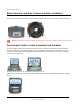
GE Oil & Gas Dresser Commercial Rotary Meter Installation Installation Examples The following pictures show typical residential 100G installations.
GE Oil & Gas Dresser Commercial Rotary Meter Installation Programming the 100G Gas ERT Module Assembly Program the 100G, 100G Datalogging, 100G DLN, or 100G DLT ERT modules using: • • • An FC200SR handheld computer with Field Deployment Manager (FDM) software version 1.1 or higher or A FC300 with SRead handheld computer with Field Deployment Manager (FDM) software version 1.1 or higher or A 900MHz Belt Clip Radio with Field Deployment Manager (FDM) software version 1.
GE Oil & Gas Dresser Commercial Rotary Meter Installation For 5C15 and 8C15 Rotary Meters, program as 4 dial, 2 cubic foot index. For all other residential 100G series gas ERT modules, refer to B3, LMMA, and S3A CTR/TC GE Dresser Series Register Settings and Direct Drive Programming Information on page 88. To program the 100G ERT module Program the meter drive rate into the commercial ERT module using the endpoint programming device.
GE Oil & Gas Dresser Commercial Rotary Meter Installation Settings for Series S3A Registers Model Meter Size CTR 1.5M - 11M TC Settings Number of dials: 5 Drive rate: 10 PCOMP factor: NONE 16M Number of dials: 6 Drive rate: 100 PCOMP factor: NONE 1.
GE Oil & Gas Dresser Commercial Rotary Meter Installation S3A CTR Meter Size 1.5M S3A CTR Meter Drive Rate 10 S3A TC Meter Size 1.5M S3A TC Meter Drive Rate 100 3M 10 3M 100 5M 10 5M 100 7M 10 7M 100 11M 10 11M 100 16M 100 16M 1000 Caution Drive rates in these tables are for direct-mount residential style ERTs only (NOT commercial or remote ERT modules). Note S3A rotary meters are LMMA meters retrofitted with a Series 3 accessory.
GE Oil & Gas Dresser Commercial Rotary Meter Installation Installing the Commercial Gas ERT Module Assembly on a GE Dresser Rotary Meter with an Instrument Drive The information in this section guides you through the installation of the commercial gas ERT on GE Dresser rotary meters. Note This installation procedure requires a GE Dresser rotary gas meter with an instrument drive. These instructions show an Elster American commercial ERT module.
GE Oil & Gas Dresser Commercial Rotary Meter Installation The 100G DLS ERT modules support enhanced security with the Itron Security Manager. Enabling command or enhanced security requires additional programming. Program the 100G DLS ERT modules using: • • • An FC200SR handheld computer with Field Deployment Manager (FDM) software version 3.3 or higher or An FC300 with SRead handheld computer with Field Deployment Manager (FDM) software version 3.
GE Oil & Gas Dresser Commercial Rotary Meter Installation B3, LMMA, and S3A CD/TD GE Dresser Meter Drive Rates Use the information in the following tables to program the commercial ERT modules installed on GE Dresser B3, LMMA, and S3A registers. Reference the 100G Gas ERT Module Meter Compatibility List to confirm compatibility. Warning Drive rates listed in the following tables are for commercial module programming. Do not use these settings to program residential or remote modules.
GE Oil & Gas Dresser Commercial Rotary Meter Installation To install the commercial ERT module to the meter Note A cover is installed on the commercial gas ERT module mounted to a GE Dresser Meter with S3A LMMA accessory units (or other GE Dresser adapters with odometer gauges). 1. Locate the INSTRUMENT FACE stamp (1) and position the meter with the drive dog (2) centered (as shown). Warning Handle the commercial ERT module carefully so the metal passive radiator antenna is not damaged. 2.
GE Oil & Gas Dresser Commercial Rotary Meter Installation 3. Verify the ERT wriggler and drive dog shaft are engaged by turning the commercial ERT module wriggler. When properly engaged, you will feel resistance. 4. Place the customer-supplied index mounting plate on the ERT and install the four mounting screws. Do not disturb the shaft alignment. 5. Install the four ERT module mounting screws (supplied with the commercial ERT). Tighten mounting screws in an alternating, diagonal pattern.
GE Oil & Gas Dresser Commercial Rotary Meter Installation Completed Installation Examples 100G Elster American commercial gas ERT module mounted on a GE Dresser Meter with an instrument drive 100G Sensus commercial gas ERT module mounted on a GE Dresser meter with an instrument drive TDC-0823-014 100G Series Gas ERT Module Installation Guide, Direct Mount Proprietary and Confidential 96
CHAPTER 9 Romet Commercial Rotary Meter Installation This chapter provides the instructions to mount residential 100G ERT modules on the Romet RM commercial rotary meters. Only Elster American version residential 100G ERT modules are compatible with Romet RM rotary gas meters.This chapter provides the instructions to mount an Elster American residential 100G ERT module on Romet AMR-ready rotary commercial meters. Installation requires an AMR adapter kit supplied by Romet.
Romet Commercial Rotary Meter Installation The 100G DLS ERT modules support enhanced security with the Itron Security Manager. Enabling command or enhanced security requires additional programming. Program the 100G DLS ERT modules using: • • • An FC200SR handheld computer with Field Deployment Manager (FDM) software version 3.3 or higher or An FC300 with SRead handheld computer with Field Deployment Manager (FDM) software version 3.
Romet Commercial Rotary Meter Installation Installing the Residential ERT Module Assembly to the Romet After the 100G ERT module is programmed, attach the module to the Romet rotary meter. To attach the ERT module to the Romet rotary meter Refer to the Installation Example on page 97. The ERT module must be mounted on the adapter plate in an upright position. Follow the alignment of the mounting components shown in the exploded installation illustration (step 2). 1.
Index 100G DLS Gas ERT Module security • 2 100G meter compatibility list • 4 installing the commercial gas ERT on a Dresser Rotary Meter with an instrument drive • 91 Itron (Sprague) meter installation • 31 Itron Security Manager • 2 A N Symbols & Numbers about the 100G gas ERT module • 1 assembling the ERT module and index • 18 attaching the 100G assembly to the meter • 35, 29, 22, 54 attaching the 100G assembly to the Sensus meter • 29 attaching the 100G to the commercial meter • 78, 62 attaching th