
User's Manual

National (Lancaster) Meter Installation
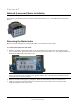
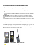
4. Attach the screw to the ERT housing's right-index mounting post just enough to hold the screw and the
right end of the index in place.
5. For indexes with legs (mounting slots), screw one 10 - 20 x 3/8-inch screw (SCR-0017-001, see
Installation Prerequisites on page 14 for screw information) into the right index mounting post one or two
turns. Do not completely tighten the screw.
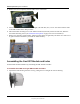
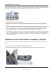
6. Place the right index mounting screw slot under the screw head. Do not completely tighten the screw.
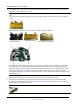
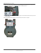
7. Carefully slide the index drive post into the ERT shaft slot. Verify positive engagement of the index
wriggler to the ERT shaft. (The following illustrations show index to shaft placement with positive
engagement.)
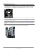
Warning Verify the index drive slot engages with the 100G shaft. Failure to mate the ERT shaft with the
index drive post (or slot) can cause binding and lead to poor registration or meter failure.
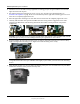
8. Install and tighten the left index mounting screw (for indexes with either mounting screw slots or holes).
Tighten the right index mounting screw. Tighten each index mounting screw evenly.
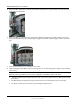
Warning Slide indexes with mounting screw slots all the way to the right. Verify the ERT module shaft
is aligned with the index drive post. Hold the index tightly in place while you secure the index mounting
screws.
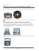
9. Slide the ERT module cover over the index and housing. Verify the cover is installed correctly. The ERT
module label should be clearly visible and easily read.
TDC-0823-014 100G Series Gas ERT Module Installation Guide, Direct Mount 52
Proprietary and Confidential