
User's Manual

National (Lancaster) Meter Installation
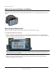
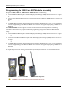
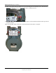
2. Carefully place the 100G on the meter.
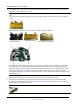
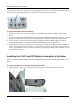
Warning Failure to correctly align the meter drive post and ERT module wriggler can cause binding and
lead to poor registration or meter failure. If there is a gap between the ERT module gasket and the meter,
it may be the wriggler of the ERT module is dead-headed against the meter drive dog as shown in the
following illustration.
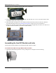
Remove the 100G assembly and repeat the alignment procedure. You must engage the meter drive dog in
the ERT module wriggler.
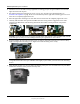
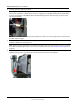
3. Insert the right module mounting screw and tighten the screw until the gasket is against the meter. Do not
completely tighten the mounting screw.
Note Use the original mounting screws to mount the 100G if they were the correct size and not corroded.
If you discarded the original screws, use the correct replacement screws (see Installation Prerequisites on
page 14
.)
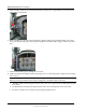
4. Slightly raise the left side of the ERT module (the module will rotate on the right screw) until the left ERT
module mounting hole is approximately 1/4-inch above the left meter mounting hole.
TDC-0823-014 100G Series Gas ERT Module Installation Guide, Direct Mount 55
Proprietary and Confidential