
User's Manual
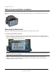

National (Lancaster) Meter Installation
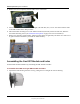
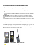
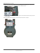
5. Rotate the ERT module down until the ERT module mounting hole is approximately 1/4-inch below the
meter index mounting hole.
6. Rotate the ERT up to align the left mounting holes. Raising and lowering the ERT module on the meter
drive post facilitates the proper positioning and engagement of ERT module wriggler with the meter drive
post.
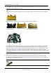
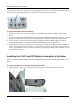
7. Insert the left mounting screw and tighten a few turns.
8. Tighten the right and left ERT-to-meter mounting screws in an alternating pattern. Tighten each mounting
screw evenly.
Important Meter manufacturers: torque the mounting screws 15 to 20 inch-pounds.
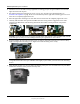
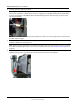
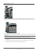
Tip The following conditions ensure proper engagement of the ERT module to the meter:
• The ERT module fits flush against the meter body--there are no gaps between the ERT gasket and the
meter body.
• The ERT module mounting holes align with the index cover mounting holes on the meter body.
• The meter test dial moves in relation to gas flowing through the meter.
TDC-0823-014 100G Series Gas ERT Module Installation Guide, Direct Mount 56
Proprietary and Confidential