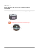
CHAPTER 6 Elster American and Itron Actaris Commercial Meter Installation This chapter provides instructions to install the 100G Datalogging Gas Endpoint on Elster American and Itron/Actaris Commercial Meters. Warning Handle the commercial 100G Datalogging Gas Endpoint carefully so the metal passive radiator antenna is not damaged.
Chapter 6 Elster American and Itron Actaris Commercial Meter Installation Removing the Index/ Index Assembly from the Meter Commercial 100G Datalogging Gas Endpoints can be mounted on Elster American Meters in various configurations. These instructions show metal mounting plates without tamper seal cups and plastic mounting plates with tamper seal cups to represent mounting plate options.
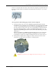
Removing the Index/ Index Assembly from the Meter To Remove the Index Assembly 1. Remove any tamper seals (1) (or wire seals) from the index cover and mounting plate screws (2). Set the index/cover assembly aside. You will re-install it later in these instructions. 2. Remove the index cover screws from the meter. Verify screws are 1/2" long and are not corroded.
Chapter 6 Elster American and Itron Actaris Commercial Meter Installation 3. Remove the gasket from the index cover mounting plate (if applicable). Set it aside where it will not be damaged. Remove the tamper seals from the mounting plate. Remove the mounting plate screws and separate the mounting plate from the meter. Place the mounting plate where it will not be damaged. You will use it later in this installation.
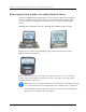
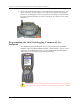
Programming the 100G Datalogging Commercial Gas Endpoint Take note of the index drive rate shown on the index. The endpoint is programmed based on the drive rate. Elster American commercial meter index drive rates may be 5-, 10- or 100 cubic feet. To Program the 100G Datalogging Commercial Gas Endpoint 1. Program the index drive rate into the 100G Datalogging Gas Endpoint using the FC200SR. For all programming and "Check Endpoint" operations, hold the FC200SR as close to vertical as possible.
Chapter 6 Elster American and Itron Actaris Commercial Meter Installation 3. Read the 100G Datalogging Gas Endpoint using the FC200SR. • If the read result is higher than the number programmed in Step 1, the 100G Datalogging Gas Endpoint is counting correctly. • If the read result is not higher than the number programmed in Step 1, replace the 100G Datalogging Gas Endpoint.
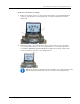
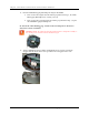
Programming the 100G Datalogging Commercial Gas Endpoint 2. Align the endpoint so the screw holes line up with the meter's top screw holes. Carefully lower the endpoint on the meter with the wriggler notches lining up with the meter's wriggler teeth. Warning The INLET label on the 100G Datalogging Commercial Gas Endpoint must line up with the INLET label on the meter case. 3. Verify the bottom of the endpoint and the top of the meter meet. The endpoint housing should rest on top of the meter without gaps.
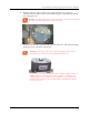
Chapter 6 Elster American and Itron Actaris Commercial Meter Installation 4. Place the index cover mounting plate on the commercial 100G Datalogging Gas Endpoint so the printing "FLOW FRONT AL800 AL1000 AL1400 AL2300 AL5000 TURBINE ROTARY" stamped on the plate is toward the front of the meter. (A gap between the mounting plate and meter at the screw locations is normal.) 5.
Programming the 100G Datalogging Commercial Gas Endpoint To Attach the Index/Cover Assembly on the Elster American Commercial Meter 1. Place the mounting plate gasket (previously removed) on the index cover mounting plate. Align the gasket and index cover mounting plate screw holes. 2. Place the index/cover assembly on the index mounting plate. (The index must face the direction it faced before removal.) Attach the index/cover assembly on the mounting plate using original index screws.
Chapter 6 Elster American and Itron Actaris Commercial Meter Installation 5. Install new tamper or wire seals. If tamper seals are installed, press into place with an 11/32 nut driver or similar blunt tool. Crimp the seal if utility-approved wire seals are installed. This completes installation of the 100G Datalogging Commercial Gas Endpoint on an Elster American Commercial meter.
Installing the 100G Datalogging Commercial Gas Endpoint on an Itron/Actaris Commercial Meter Installing the 100G Datalogging Commercial Gas Endpoint on an Itron/Actaris Commercial Meter This section provides instructions for installing the 100G Datalogging Commercial Gas Endpoint on Itron/Actaris 675A, 800A, and 1000A commercial meters. Installation requires an Itron/Actaris adapter kit from Itron/Actaris.
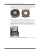
Chapter 6 Elster American and Itron Actaris Commercial Meter Installation To Attach the 100G Datalogging Commercial Gas Endpoint to the Meter 1. Turn the 100G Datalogging Commercial Gas Endpoint over and place the four mounting screw bushings into the screw holes on the endpoint. 2. Turn the 100G Datalogging Commercial Gas Endpoint on its side and align the wriggler with the Itron-Actaris Commercial meter's drive dog.
Installing the 100G Datalogging Commercial Gas Endpoint on an Itron/Actaris Commercial Meter 3. Inlet lettering on the 100G Datalogging Commercial Gas Endpoint must line up with Inlet lettering on the meter. Slowly lower the endpoint on the Itron-Actaris Commercial meter aligning the drive dog and wriggler. The endpoint housing should rest on the top of the meter without gaps. Warning Do not press down on the 100G Datalogging Gas Endpoint if a gap exists between the endpoint and the meter.
Chapter 6 Elster American and Itron Actaris Commercial Meter Installation 2. Place the extension driver on the 100G Datalogging Commercial Gas Endpoint wriggler. 3. Align the index wriggler with the commercial 100G Datalogging Commercial Gas Endpoint wriggler driver extension. 4. Install the two index mounting screws. Tighten the first screw two or three turns. Install second screw and tighten to secure. Tighten the first screw to a snug fit. Each index mounting screw must be tightened evenly.
Installing the 100G Datalogging Commercial Gas Endpoint on an Itron/Actaris Commercial Meter 5. Place the index cover over the index with the clear side covering the index dials for easy reading. Align the holes in the index cover with the endpoint adapter plate mounting holes. Secure with the four mounting screws from the adapter kit. Tighten the mounting screws in a diagonal alternating pattern. • Insert the first screw and tighten enough to hold the index in place.
Chapter 6 Elster American and Itron Actaris Commercial Meter Installation This completes installation of the commercial 100G Datalogging Gas Endpoint on the ItronActaris Commercial meter.
CHAPTER 7 Sensus/Rockwell Commercial Meter Installation This chapter provides instructions to install the 100G Datalogging Commercial Gas Endpoint on a Commercial Sensus/Rockwell diaphragm meter. Removing the Index/ Index Assembly from the Meter 100G Datalogging Commercial Gas Endpoints can be mounted on Sensus/Rockwell Commercial Meters in various configurations. These instructions show the index assembly mounted without a mounting plate.
Chapter 7 Sensus/Rockwell Commercial Meter Installation 2. Remove the index screws from the meter. Set the index cover aside where it will not be damaged or fill with dirt, rain or snow. You will re-install the index later in this procedure. Note Properly dispose all unused screws, old index covers, gaskets, tamper seals, and other leftover materials. Do not leave materials on customer premises.
Programming the 100G Datalogging Gas Endpoint Take note of the index drive rate shown on the index. The endpoint is programmed based on the drive rate. Sensus/Rockwell commercial meter index drive rates may be 5-, 10- or 100cubic feet. The seven-dial index shown is a 100-cubic feet drive rate. To Program the 100G Datalogging Commercial Gas Endpoint 1. Program the index drive rate into the commercial endpoint using the FC200SR.
Chapter 7 Sensus/Rockwell Commercial Meter Installation Attaching the 100G Datalogging Commercial Endpoint to a Sensus/Rockwell Commercial Diaphragm Meter Warning Handle the 100G Datalogging Commercial Gas Endpoint carefully so the metal passive radiator antenna is not damaged. To Attach the 100G Datalogging Commercial Endpoint 1. Tilt the 100G Datalogging Commercial Gas Endpoint at an angle and turn the wriggler until the drive notches line up with the meter wriggler's drive teeth. 2.
Attaching the 100G Datalogging Commercial Endpoint to a Sensus/Rockwell Commercial Diaphragm Meter 3. Verify the bottom of the 100G Datalogging Commercial Gas Endpoint and the top of the meter meet. The endpoint housing should rest on top of the meter without gaps. Warning Do not press down on the 100G Datalogging Commercial Gas Endpoint if a gap exists between the endpoint and the meter. A gap may be caused by misalignment of the endpoint wriggler and meter wriggler's drive teeth.
Chapter 7 Sensus/Rockwell Commercial Meter Installation 5. Install the index cover. For index covers with flat-surface screw holes, use screws (SCR-0062-002), flat washers (WSH-0020-005), and cork washers (WSH-0032-001). For index covers with tamper seal cups, use screws, (AS-568A-011, 5/16" ID x 7/16 OD) o-rings, and tamper seals. 6. Place new tamper seals over screws (if mounting plate has tamper seal cups) and press into place with an 11/32" nut driver or similar blunt tool.
Attaching the 100G Datalogging Commercial Endpoint to a Sensus/Rockwell Commercial Diaphragm Meter This completes installation of the 100G Datalogging Gas Endpoint on the Sensus/Rockwell Commercial Diaphragm meter.
Chapter 7 80 Sensus/Rockwell Commercial Meter Installation 100G Datalogging Installation Guide - Direct Mount
CHAPTER 8 Dresser ROOTS Commercial Rotary Meter Installation This chapter provides the instructions to mount 100G Datalogging Gas Endpoints (residential and commercial) on Dresser ROOTs Commercial Rotary Meters. Some commercial AMR applications require a Dresser ROOTS Rotary Meter with a residential 100G Datalogging Gas Endpoint. Only Elster American version residential 100G Datalogging Gas Endpoints are compatible with Dresser ROOTS series rotary gas meters.
Chapter 8 Dresser ROOTS Commercial Rotary Meter Installation Installation Examples The following pictures show typical installations.
Programming the 100G Datalogging Gas Endpoint Assembly Programming the 100G Datalogging Gas Endpoint Assembly The 100G Datalogging Gas Endpoint must be programmed with the FC200SR handheld computer loaded with EndPoint-Link® or Point-Link Pro® software version 5.3 or later. See the Endpoint-Link v5.3 (or later) Endpoint Programming Guide (TDC-0744) for more complete programming information. Caution The 100G Datalogging Gas Endpoint must be programmed before use.
Chapter 8 Dresser ROOTS Commercial Rotary Meter Installation 2. Slowly turn the endpoint's drive wriggler two turns in the direction shown on the index drive rate. This verifies the endpoint is counting properly after assembly. Caution Do not turn the drive wriggler faster than one turn per second. 3. Read the 100G Datalogging Gas Endpoint using the FC200SR. 84 • If the read result is higher than the number programmed in Step 1, the 100G Datalogging Gas Endpoint is counting correctly.
B3, LMMA, and S3A CTR/TC Dresser ROOTS Series Register Settings and Direct Drive Programming Information B3, LMMA, and S3A CTR/TC Dresser ROOTS Series Register Settings and Direct Drive Programming Information Use the information in the following tables to program Dresser Roots Series B3, LMMA, and S3A Non-compensated Counter (CTR) and Temperature Compensated Counter (TC) registers. Reference the Meter Compatibility List on page 2 to confirm compatibility.
Chapter 8 Dresser ROOTS Commercial Rotary Meter Installation Settings for LMMA Registers Model CTR Meter size 1.5M-11M Settings Number of dials: 5 Drive rate: 10 PCOMP factor: NONE 16M Number of dials: 6 Drive rate: 100 PCOMP factor: NONE TC 1.5M-11M Number of dials: 5 Drive rate: 50 PCOMP factor: NONE 16M Number of dials: 6 Drive rate: 500 PCOMP factor: NONE Settings for Series S3A Registers Model CTR Meter Size 1.
B3, LMMA, and S3A CTR/TC Dresser ROOTS Series Register Settings and Direct Drive Programming Information B3, LMMA and S3A CTR/TC Meter Drive Rates: Residential Direct Drive Programming* B3 CTR Meter Size 8C B3 CTR Meter Drive Rate 10 11C 10 15C 10 2M 10 3M 10 5M 10 7M 10 11M 10 16M 100 23M 100 38M 100 56M 100 Drive rates in this table are for direct-mount residential style endpoints only (NOT commercial or remote endpoints).
Chapter 8 Dresser ROOTS Commercial Rotary Meter Installation LMMA TC Meter Size 1.5M LMMA TC Meter Drive Rate 50 3M 50 5M 50 7M 50 11M 50 16M 500 S3A CTR Meter Size 1.5M S3A CTR Meter Drive Rate 10 3M 10 5M 10 7M 10 11M 10 16M 100 S3A TC Meter Size 1.5M S3A TC Meter Drive Rate 100 3M 100 5M 100 7M 100 11M 100 16M 1000 Note S3A rotary meters are LMMA meters retrofitted with Series 3 End Bell Adapter.
Installing the Residential 100G Datalogging Gas Endpoint Assembly to the Dresser ROOTS Rotary Meter Installing the Residential 100G Datalogging Gas Endpoint Assembly to the Dresser ROOTS Rotary Meter After 100G Datalogging Gas Endpoint programming is complete, attach the 100G Datalogging residential endpoint assembly to the Dresser ROOTS Rotary Meter. This mounting procedure applies to B3 CTR/TC, LMMA CTR/TC, and 8C15 series Dresser ROOTS Meters. To Attach the 100G Datalogging Gas Endpoint 1.
Chapter 8 Dresser ROOTS Commercial Rotary Meter Installation Installing the 100G Datalogging Commercial Gas Endpoint on a Dresser ROOTS Rotary Meter The information in this section guides you through the installation of the 100G Datalogging Commercial Gas Endpoint on Dresser ROOTS rotary meters. Note A Dresser ROOTS rotary gas meter with an instrument drive is required for this installation procedure. These instructions show an Elster American 100G Datalogging Commercial Gas Endpoint.
Installing the 100G Datalogging Commercial Gas Endpoint on a Dresser ROOTS Rotary Meter Programming the 100G Datalogging Commercial Gas Endpoint Assembly The 100G Datalogging Commercial Gas Endpoint must be programmed with the FC200SR handheld computer loaded with EndPoint-Link® or Point-Link Pro® software version 5.3 or later. See the Endpoint-Link v5.3 (or later) Endpoint Programming Guide (TDC-0744) for more complete programming information.
Chapter 8 Dresser ROOTS Commercial Rotary Meter Installation 2. Slowly turn the endpoint's drive wriggler two turns in the direction shown on the index drive rate. This verifies the endpoint is counting properly after assembly. Caution Do not turn the drive wriggler faster than one turn per second. 3. Read the 100G Datalogging Commercial Gas Endpoint using the FC200SR.
Installing the 100G Datalogging Commercial Gas Endpoint on a Dresser ROOTS Rotary Meter B3, LMMA, and S3A CD/TD Dresser ROOTS Series Meter Drive Rates Use the information in the following tables to program 100G Datalogging Commercial Endpoints installed on Dresser Roots Series B3, LMMA, and S3A Non-compensated Counter with Instrument Drive (CD) and Temperature Compensated Counter with Instrument Drive (TD) registers. Reference the Meter Compatibility List on page 2 to confirm compatibility.
Chapter 8 Dresser ROOTS Commercial Rotary Meter Installation LMMA CD Meter Size 1.5M LMMA CD Meter Drive Rate 10 3M 10 5M 10 7M 10 11M 10 16M 100 LMMA TD Meter Size 1.5M LMMA TD Meter Drive Rate 100 3M 100 5M 100 7M 100 11M 100 16M 1000 S3A CD Meter Size 1.5M S3A CD Meter Drive Rate 100 3M 100 5M 100 7M 1000 11M 100 16M 1000 S3A TD Meter Size 1.
Installing the 100G Datalogging Commercial Gas Endpoint on a Dresser ROOTS Rotary Meter To Attach the 100G Datalogging Commercial Gas Endpoint to the Meter Note A cover is installed on the 100G Datalogging Commercial Gas Endpoint mounted to a Dresser ROOTS Meter with S3A LMMA Accessory Units (or other Dresser ROOTs adapters with odometer gauges). 1. Locate the INSTRUMENT FACE stamp (2) and position the meter with the drive dog (1) aligned (as shown).
Chapter 8 Dresser ROOTS Commercial Rotary Meter Installation 3. Verify the endpoint wriggler and drive dog shaft are engaged by turning the commercial endpoint wriggler. When properly engaged, you will feel resistance. 4. Place the index mounting plate on the endpoint and install the four mounting screws. Do not disturb the shaft alignment. 5. Install the four 100G Datalogging Commercial Gas Endpoint mounting screws (supplied with the commercial endpoint).
Installing the 100G Datalogging Commercial Gas Endpoint on a Dresser ROOTS Rotary Meter Completed Installation Examples 100G Datalogging Elster American Commercial Gas Endpoint mounted on a Dresser ROOTS Meter 100G Datalogging Sensus/Rockwell Commercial Gas Endpoint mounted on a Dresser ROOTS Meter 100G Datalogging Installation Guide - Direct Mount 97