
User's Manual


Electronic Volume Corrector and Instrument Installation
TDC-0824-003 100G Datalogging FN ERT Module Installation Guide - Remote Mount 48
Proprietary and Confidential
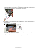
4. Insert the #10 spacers into the four mounting holes on the back of the IMC\W2.
Caution Upright vertical positioning is very important because:
• 100G Datalogging FN remote ERT modules are designed with the antenna in a vertical direction so the
antenna is parallel to the reading device (which has a vertical antenna). Matching antenna polarity can
greatly affect RF performance and enable easy ERT module reading.
• 100G Datalogging FN remote ERT modules are designed so the tilt tamper is vertical. It is important to
maintain vertical positioning in the field to enable tilt tamper stability.
• 100G Datalogging FN remote ERT module batteries must be vertical (installed with the positive
terminal upward) or battery life is compromised.
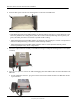
5. Secure the endpoint/bracket assembly on the IMC\W2 using four endpoint/mounting bracket screws (M6
x 20 mm).
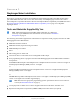
6. There are two options to connect the 100G Datalogging FN remote ERT module to Dresser ROOTS to the
IMC\W2:
1. For the Amphenol connector: plug the connector from the Itron ERT module to the IMC\W2 volume
input connector.