
Installation Guide
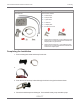
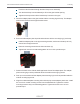
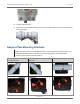
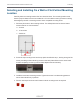
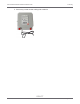
Table Of Contents
- Cellular 500G Module Remote Mount Installation Guide
- Contents
- New in This Document
- 1 Introduction
- 2 Mounting
- 3 Programming
- 4 Specific Meter Manufacturer Installation
- 5 Using Gel-cap Connectors to Complete Wiring Connections
- 6 Optional Sealant Application Instructions
- A Important Safety and Compliance Information
- U.S. and Canadian Patent Numbers
- USA, FCC Part 15 Spectrum Compliance
- Modifications, Repairs, Installation, and Removal
- Canada, ISED Spectrum Compliance
- RF Exposure (FCC/ISED)
- Transportation Classification
- Lithium Battery Safety
- Equipment Repairs
- Intrinsic Safety
- Electrostatic Ignition Hazard
- Module Cleaning
- Do Not Drop

Selecting and Installing On a Wall or Flat Vertical Mounting
Location
Carefully select a mounting location free from electrical wires. The mounting location must
have the proper clearance to accommodate the 1.5 inch module mounting screws so nothing
is damaged by the drill or mounting screws. Use a compatible mounting screw.
1. Drill three pilot holes in the mounting surface. The drilled pilot holes for the two bottom
screws must be on a horizontal line.
a. 3 inches
b. 11/16inches
c. 3/8inches
2. Screw the top mounting screw into the top pilot hole drilled in step 1, leaving enough of the
screw protruding so the module lug recess on the back plate slides over the screw head
and fits completely into the lug recess. Make adjustments as necessary.
3. Install the two bottom mounting screws. Tighten the screws in an alternating pattern to
secure the module firmly in position.
4. Place a new tamper seal over each bottom module mounting screw as required.
Cellular 500G Module Remote Mount Installation Guide 2 Mounting
October 11, 2021 815-0622-00 REV 000 Itron, Inc. Page 16 of 99
DRAFT