
Installation Guide
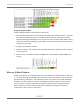
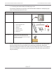
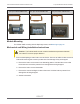
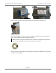
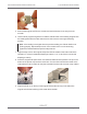
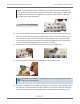
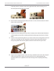
Table Of Contents
- Cellular 500G Module Remote Mount Installation Guide
- Contents
- New in This Document
- 1 Introduction
- 2 Mounting
- 3 Programming
- 4 Specific Meter Manufacturer Installation
- 5 Using Gel-cap Connectors to Complete Wiring Connections
- 6 Optional Sealant Application Instructions
- A Important Safety and Compliance Information
- U.S. and Canadian Patent Numbers
- USA, FCC Part 15 Spectrum Compliance
- Modifications, Repairs, Installation, and Removal
- Canada, ISED Spectrum Compliance
- RF Exposure (FCC/ISED)
- Transportation Classification
- Lithium Battery Safety
- Equipment Repairs
- Intrinsic Safety
- Electrostatic Ignition Hazard
- Module Cleaning
- Do Not Drop

4-hole front cover gasket:
Itron part number FAB-0014-003
2-hole front cover gasket:
Itron part number FAB-0014-002
1-hole front cover gasket:
Itron part number FAB-0014-001
Module Mounting
For Cellular 500G mounting with the diaphragm meter, see Mounting on page 12.
Mechanical and Wiring Installation Instructions
Caution: The Cellular 500G encoder must be installed at temperatures between
40° and 95°F to ensure proper adhesion.
1. Remove the diaphragm meter index cover and index. Use care to hold the index cover and
index while loosening the screws to protect them from damage if they are dropped.
a. Remove the index cover screws in an alternating pattern. Hold the index cover while
the screws are removed to protect it from damage due to being dropped.
b. Remove the index cover and set aside.
c. Remove the screws holding the index to the meter. Hold the index to protect it from
damage due to being dropped.
d. Set the index aside.
Cellular 500G Module Remote Mount Installation Guide 4 Specific Meter Manufacturer Installation
October 11, 2021 815-0622-00 REV 000 Itron, Inc. Page 25 of 99
DRAFT