
Installation Guide
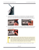
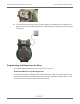

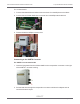
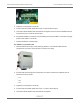
Table Of Contents
- Cellular 500G Module Remote Mount Installation Guide
- Contents
- New in This Document
- 1 Introduction
- 2 Mounting
- 3 Programming
- 4 Specific Meter Manufacturer Installation
- 5 Using Gel-cap Connectors to Complete Wiring Connections
- 6 Optional Sealant Application Instructions
- A Important Safety and Compliance Information
- U.S. and Canadian Patent Numbers
- USA, FCC Part 15 Spectrum Compliance
- Modifications, Repairs, Installation, and Removal
- Canada, ISED Spectrum Compliance
- RF Exposure (FCC/ISED)
- Transportation Classification
- Lithium Battery Safety
- Equipment Repairs
- Intrinsic Safety
- Electrostatic Ignition Hazard
- Module Cleaning
- Do Not Drop

21. Install a strain-relief cable tie about 1.25 inches from the encoder cable’s stripped end.
The cable tie must be inside the index cover after the cover is installed on the meter.
Remove any excess cable tie with side-cutting pliers and dispose of the excess cable tie.
22. Remove the protective backing on the replacement gasket to expose the adhesive side of
the gasket. Align the gasket (1), encoder cable (2), and cable tie (for strain-relief) (3) on
the meter as shown.
Caution: Route the encoder cable inside the index cover to provide strain relief
(minimize pulling or twisting on the encoder). Verify that the strain-relief cable tie
on the encoder cable is inside the index cover when the cover is installed on the
meter. The gasket must align with the index cover screw holes and adhere to the
meter face to ensure a proper seal after the index cover is installed.
23. Install the four index cover screws and tighten just enough to hold the screws in place.
Cellular 500G Module Remote Mount Installation Guide 4 Specific Meter Manufacturer Installation
October 11, 2021 815-0622-00 REV 000 Itron, Inc. Page 31 of 99
DRAFT