
Installation Guide
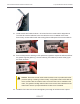
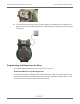
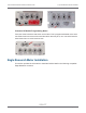
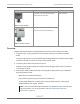

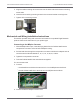
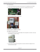
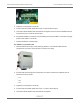
Table Of Contents
- Cellular 500G Module Remote Mount Installation Guide
- Contents
- New in This Document
- 1 Introduction
- 2 Mounting
- 3 Programming
- 4 Specific Meter Manufacturer Installation
- 5 Using Gel-cap Connectors to Complete Wiring Connections
- 6 Optional Sealant Application Instructions
- A Important Safety and Compliance Information
- U.S. and Canadian Patent Numbers
- USA, FCC Part 15 Spectrum Compliance
- Modifications, Repairs, Installation, and Removal
- Canada, ISED Spectrum Compliance
- RF Exposure (FCC/ISED)
- Transportation Classification
- Lithium Battery Safety
- Equipment Repairs
- Intrinsic Safety
- Electrostatic Ignition Hazard
- Module Cleaning
- Do Not Drop

4. Programming the Cellular 500G. Programming requires an Itron programming device (for
example, an FC300SR). For programming information, see Programming on page 18.
Cellular 500G configuration with the meter is dependent on your system application. See the
Eagle Research meter product documentation for the Eagle Research Field Manager
database configuration information.
This mounting information describes installation for two Cellular 500Gs—one for corrected
reads and one for uncorrected reads. Installation is the same for both configurations
(corrected or uncorrected). Eagle Research meter outputs are optically isolated from the
meter control board and from each other. The volume corrector software configuration
controls the port operation. Follow the Eagle Research documentation and these Itron
instructions to ensure the correct compatibility and installation.
Mounting Instructions
Note: These instructions show the Eagle Research MPplus volume corrector. Installation
is the same for the XARTU-1 corrector.
1. Mount a Cellular 500G on each end of the mounting rail using the mounting screws
supplied with the modules.
Note: The notch in the mounting rail is the front bottom of the rail. The modules mount
to the back of the mounting rail.
2. Insert tamper seals into the tamper seal mounting cups on the Cellular 500Gs.
3. With the corrector facing forward, align the corrector mounting holes with the index drive
mounting holes.
4. Insert the corrector’s mounting screws in the front corrector and index mounting holes.
Loosely tighten the front two mounting screws.
Cellular 500G Module Remote Mount Installation Guide 4 Specific Meter Manufacturer Installation
October 11, 2021 815-0622-00 REV 000 Itron, Inc. Page 35 of 99
DRAFT