
Installation Guide
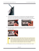
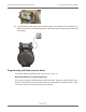
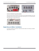
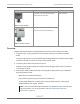

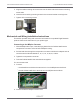
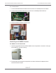
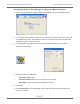
Table Of Contents
- Cellular 500G Module Remote Mount Installation Guide
- Contents
- New in This Document
- 1 Introduction
- 2 Mounting
- 3 Programming
- 4 Specific Meter Manufacturer Installation
- 5 Using Gel-cap Connectors to Complete Wiring Connections
- 6 Optional Sealant Application Instructions
- A Important Safety and Compliance Information
- U.S. and Canadian Patent Numbers
- USA, FCC Part 15 Spectrum Compliance
- Modifications, Repairs, Installation, and Removal
- Canada, ISED Spectrum Compliance
- RF Exposure (FCC/ISED)
- Transportation Classification
- Lithium Battery Safety
- Equipment Repairs
- Intrinsic Safety
- Electrostatic Ignition Hazard
- Module Cleaning
- Do Not Drop

For corrected reads
7. Connect the twisted blue and white wires to terminal 15 on the MPplus terminal block.
8. Connect the red Cellular 500G wire to terminal 16 on the MPplus terminal block.
9. Close and latch the MPplus corrector door.
Connecting to the XARTU Corrector
For XARTU-1 uncorrected reads
1. Insert the flying leads from the Cellular 500G into the compression connector on the right
of the XARTU-1 corrector housing.
2. Pull the lead wires through the compression connector until there is adequate wire to
reach the K2 terminal port.
Cellular 500G Module Remote Mount Installation Guide 4 Specific Meter Manufacturer Installation
October 11, 2021 815-0622-00 REV 000 Itron, Inc. Page 37 of 99
DRAFT