
Installation Guide
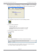
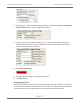

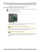

Table Of Contents
- Cellular 500G Module Remote Mount Installation Guide
- Contents
- New in This Document
- 1 Introduction
- 2 Mounting
- 3 Programming
- 4 Specific Meter Manufacturer Installation
- 5 Using Gel-cap Connectors to Complete Wiring Connections
- 6 Optional Sealant Application Instructions
- A Important Safety and Compliance Information
- U.S. and Canadian Patent Numbers
- USA, FCC Part 15 Spectrum Compliance
- Modifications, Repairs, Installation, and Removal
- Canada, ISED Spectrum Compliance
- RF Exposure (FCC/ISED)
- Transportation Classification
- Lithium Battery Safety
- Equipment Repairs
- Intrinsic Safety
- Electrostatic Ignition Hazard
- Module Cleaning
- Do Not Drop

8. Enable K2 (4, 5, 6) and set additional parameters are required in the Uncorrected Pulse
Output Setup section in the lower right of the window.
9. Set the Primary Pulse Output to Enable K1 (1, 2, 3) and the Optional Pulse Output to
Disable (unless it is used for another application) in the Corrected Pulse Output Setup
section in the lower left of the window.
10. Click Send All Changes.
11. Verify that all parameters are completed and correct.
12. Click Disconnect.
Programming Notes
During Cellular 500G programming for use with the Eagle Research corrector, verify that the
module drive rate settings match those set in the corrector. For example, set the module drive
rate for 1000 CF when the Eagle Research corrector drive rate is set for 1000 CF.
Cellular 500G Module Remote Mount Installation Guide 4 Specific Meter Manufacturer Installation
October 11, 2021 815-0622-00 REV 000 Itron, Inc. Page 43 of 99
DRAFT