
Installation Guide
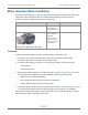

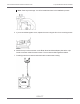
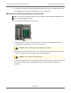
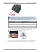

Table Of Contents
- Cellular 500G Module Remote Mount Installation Guide
- Contents
- New in This Document
- 1 Introduction
- 2 Mounting
- 3 Programming
- 4 Specific Meter Manufacturer Installation
- 5 Using Gel-cap Connectors to Complete Wiring Connections
- 6 Optional Sealant Application Instructions
- A Important Safety and Compliance Information
- U.S. and Canadian Patent Numbers
- USA, FCC Part 15 Spectrum Compliance
- Modifications, Repairs, Installation, and Removal
- Canada, ISED Spectrum Compliance
- RF Exposure (FCC/ISED)
- Transportation Classification
- Lithium Battery Safety
- Equipment Repairs
- Intrinsic Safety
- Electrostatic Ignition Hazard
- Module Cleaning
- Do Not Drop

Mounting Instructions
1. Remove the meter’s top plate by removing the two 5 mm screws and carefully prying up on
the plate. The plate is secured with an O-ring seal. Remove the O-ring from the plate.
Caution: If the O-ring is damaged during removal, obtain a replacement from
Elster American Meter Co.
2. Look into the meter tower and find the meter switch lead and connector (4-pin).
3. If the lead and connector are not visible or cannot be found, remove the four 5 mm
mounting screws and the register cover. The meter switch lead and connector will be
visible inside the cover.
4. Feed the lead and connector into the register cover tower.
Cellular 500G Module Remote Mount Installation Guide 4 Specific Meter Manufacturer Installation
October 11, 2021 815-0622-00 REV 000 Itron, Inc. Page 45 of 99
DRAFT