
Installation Guide
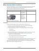

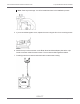
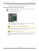
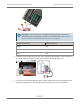

Table Of Contents
- Cellular 500G Module Remote Mount Installation Guide
- Contents
- New in This Document
- 1 Introduction
- 2 Mounting
- 3 Programming
- 4 Specific Meter Manufacturer Installation
- 5 Using Gel-cap Connectors to Complete Wiring Connections
- 6 Optional Sealant Application Instructions
- A Important Safety and Compliance Information
- U.S. and Canadian Patent Numbers
- USA, FCC Part 15 Spectrum Compliance
- Modifications, Repairs, Installation, and Removal
- Canada, ISED Spectrum Compliance
- RF Exposure (FCC/ISED)
- Transportation Classification
- Lithium Battery Safety
- Equipment Repairs
- Intrinsic Safety
- Electrostatic Ignition Hazard
- Module Cleaning
- Do Not Drop

8. Lubricate the O-ring with O-ring lubricant and install the O-ring on the adapter plate. Insert
the adapter plate into the tower and tighten the two 5 mm screws.
Mechanical and Wiring Installation Instructions
Note: Connection to an Elster American meter requires a cable interface compatible to an
Elster American RPM rotary meter.
1. Trim the Cellular 500G wires to 3.5 inches.
2. Carefully strip the insulation covering from the meter cable (purchased from the meter
manufacturer) approximately 1-1.5 inches from the end.
Caution: Do not cut through the individual wire insulation.
3. Separate the meter cable’s black, white, and red wires for connection to the Cellular 500G.
Cut off the unused wires even with the outer covering (insulation).
Caution: Do not strip the individual wires.
4. Connect the meter cable to the Cellular 500G wires using 3M gel-cap connectors following
the American RPM meter to Cellular 500G wire connection information and wiring
diagrams.
Cellular 500G Module Remote Mount Installation Guide 4 Specific Meter Manufacturer Installation
October 11, 2021 815-0622-00 REV 000 Itron, Inc. Page 47 of 99
DRAFT