
Installation Guide
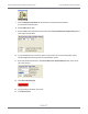
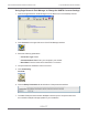
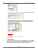
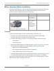

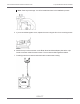
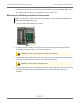
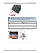
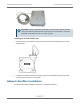

Table Of Contents
- Cellular 500G Module Remote Mount Installation Guide
- Contents
- New in This Document
- 1 Introduction
- 2 Mounting
- 3 Programming
- 4 Specific Meter Manufacturer Installation
- 5 Using Gel-cap Connectors to Complete Wiring Connections
- 6 Optional Sealant Application Instructions
- A Important Safety and Compliance Information
- U.S. and Canadian Patent Numbers
- USA, FCC Part 15 Spectrum Compliance
- Modifications, Repairs, Installation, and Removal
- Canada, ISED Spectrum Compliance
- RF Exposure (FCC/ISED)
- Transportation Classification
- Lithium Battery Safety
- Equipment Repairs
- Intrinsic Safety
- Electrostatic Ignition Hazard
- Module Cleaning
- Do Not Drop

Meter model Meter notes Itron part number Module notes
GasMicro Electronic
Volume Corrector
Must select two
pulses/second from pulse
output on the output
frequency menu.
ERG-7000-503 Module cut cable
requires customer-
supplied cable capable
of terminating the
module white and blue
wires at the meter
interface.
Overview
Installing the Cellular 500G to a Galvanic volume corrector involves four tasks.
1. Programming or verifying that the volume corrector is set up to work with the Cellular
500G. Programming requires a computer communication cable.
2. Connecting the module to the volume corrector. Completing the connections requires a
wire stripper and flat-tip screwdriver sized to tighten the terminal connections on the
Galvanic corrector.
3. Mounting the Cellular 500G. Select the mounting option appropriate for your installation.
See Mounting on page 12. Mounting options include:
–
Wall mount on a sheet metal surface
–
Pipe mount using the Itron pipe mount kit CFG-0005-003
4. Programming the Cellular 500G. For programming information, see Programming on page
18. Programming requires an Itron programming device (for example, an FC300SR).
Cellular 500G configuration with the meter is dependent on your system application. See the
Galvanic corrector product documentation for configuration information.
Mounting Instructions
See the Galvanic product documentation for custom mounting instructions.
Mechanical and Wiring Installation Instructions
GAS Micro wiring connections
GAS Micro corrector P13 connection 100G Module wires
Pulse output1-C C1 Blue/white
Pulse output1-E C2 Red
Cellular 500G Module Remote Mount Installation Guide 4 Specific Meter Manufacturer Installation
October 11, 2021 815-0622-00 REV 000 Itron, Inc. Page 50 of 99
DRAFT