
Installation Guide
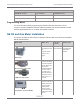
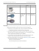
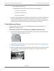


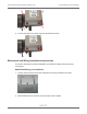
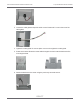
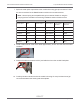
Table Of Contents
- Cellular 500G Module Remote Mount Installation Guide
- Contents
- New in This Document
- 1 Introduction
- 2 Mounting
- 3 Programming
- 4 Specific Meter Manufacturer Installation
- 5 Using Gel-cap Connectors to Complete Wiring Connections
- 6 Optional Sealant Application Instructions
- A Important Safety and Compliance Information
- U.S. and Canadian Patent Numbers
- USA, FCC Part 15 Spectrum Compliance
- Modifications, Repairs, Installation, and Removal
- Canada, ISED Spectrum Compliance
- RF Exposure (FCC/ISED)
- Transportation Classification
- Lithium Battery Safety
- Equipment Repairs
- Intrinsic Safety
- Electrostatic Ignition Hazard
- Module Cleaning
- Do Not Drop

Caution: Upright vertical positioning is critical because:
■ The 500G series modules are optimized for communication and require upright mounting. Any
other mounting position could result in reduced RF performance.
■ The Cellular 500G tilt tamper sensor requires upright mounting. Any other mounting position may
cause issues with the module’s tilt tamper detection.
GE Oil and Gas IMC/W2, or MC2 with the GE Mounting Bracket Kit
Note: This mounting option requires that you follow the installation instructions to attach
the meter maufacturer cable prior to completing this mounting option. This configuration
requires the GE mounting bracket kit available from GE Oil and Gas (GE part number
057783-000). The kit includes the listed materials.
Quantity Description GE Dresser part number
1 Mounting bracket 015951-000
1 8-32 by 7/16 inch screw 000163-277
2 8-32 by 3/4 inch screw 000163-282
3 8-32 nut 012829-005
4 #10 spacer 053669-001
5 Module/bracket mounting screw,
M6 by 20 millimeters
013444-002
Important! The GE Oil and Gas mounting bracket kit does not include the cable
required to connect the Cellular 500G to the Amphenal connector on the IMC\W2.
Completing the Bracket Installation
1. Insert the 8-32 by 7/16 inch screw (1) into the top of the mounting bracket. Insert the two 8-
32 by 3/4 inch screws (2) into the bottom of the mounting bracket.
2. Insert one 3/32 inch nut on the top 7/16 inch bracket screw. Slide the Cellular 500G
mounting lug over the top of the bracket screw and nut.
Cellular 500G Module Remote Mount Installation Guide 4 Specific Meter Manufacturer Installation
October 11, 2021 815-0622-00 REV 000 Itron, Inc. Page 54 of 99
DRAFT