
Installation Guide
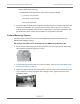


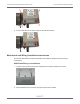
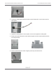
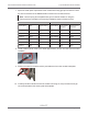
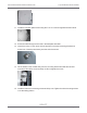
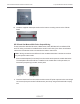
Table Of Contents
- Cellular 500G Module Remote Mount Installation Guide
- Contents
- New in This Document
- 1 Introduction
- 2 Mounting
- 3 Programming
- 4 Specific Meter Manufacturer Installation
- 5 Using Gel-cap Connectors to Complete Wiring Connections
- 6 Optional Sealant Application Instructions
- A Important Safety and Compliance Information
- U.S. and Canadian Patent Numbers
- USA, FCC Part 15 Spectrum Compliance
- Modifications, Repairs, Installation, and Removal
- Canada, ISED Spectrum Compliance
- RF Exposure (FCC/ISED)
- Transportation Classification
- Lithium Battery Safety
- Equipment Repairs
- Intrinsic Safety
- Electrostatic Ignition Hazard
- Module Cleaning
- Do Not Drop

3. Secure the bottom Cellular 500G mounting holes over the two 8-32 by 3/4 inch screws
with the remaining two 8-32 nuts.
4. Insert the #10 spacers into the four mounting holes on the back of the IMC\W2.
Caution: Upright vertical positioning is very important because the Cellular
500G is:
– designed with the antenna in a vertical direction so the antenna is parallel to the reading
device (which has a vertical antenna). Matching antenna polarity can greatly affect RF
performance and enable easy module reading.
– designed so the tilt tamper is vertical. It is important to maintain vertical positioning in the field
to enable tilt tamper stability.
– designed for installation with the batteries vertical (installed with the positive terminal
upward). Any other installation orientation will compromise battery life.
5. Secure the module/bracket assembly on the IMC\W2 using four module/mounting bracket
screws (M6 by 20 millimeters). Install tamper seals as required.
Cellular 500G Module Remote Mount Installation Guide 4 Specific Meter Manufacturer Installation
October 11, 2021 815-0622-00 REV 000 Itron, Inc. Page 55 of 99
DRAFT